Calculation of design heat load of rooms: Difference between revisions
Klintsevicho (talk | contribs) |
No edit summary Tag: Manual revert |
||
| (52 intermediate revisions by 4 users not shown) | |||
| Line 11: | Line 11: | ||
|c3 =<!--Jest kategoria -> zamienić na: "category3=" i uzupełnić link do sekcji kategorii na stronie głównej produktu--> | |c3 =<!--Jest kategoria -> zamienić na: "category3=" i uzupełnić link do sekcji kategorii na stronie głównej produktu--> | ||
|category_name3 =<!--podać nazwę kategorii "ZASTOSOWANIE"/"FUNKCJONALNOŚĆ"/...--> | |category_name3 =<!--podać nazwę kategorii "ZASTOSOWANIE"/"FUNKCJONALNOŚĆ"/...--> | ||
|version1 = | |version1 =2026-02-20 | ||
|v2 =<!--Jest wersja -> zamienić na: "version2=" i uzupełnić link do sekcji RN danego produktu--> | |v2 =<!--Jest wersja -> zamienić na: "version2=" i uzupełnić link do sekcji RN danego produktu--> | ||
|v3 =<!--Jest wersja -> zamienić na: "version2=" i uzupełnić link do sekcji RN danego produktu--> | |v3 =<!--Jest wersja -> zamienić na: "version2=" i uzupełnić link do sekcji RN danego produktu--> | ||
| Line 45: | Line 45: | ||
====Verification of thermal partition model==== | ====Verification of thermal partition model==== | ||
''<IS_TS id=BuildingStructureCalculation/>'' | During the ''<IS_TS id=BuildingStructureCalculation/>'' automatic thermal partitions are created based on structural elements and automatically recognized ''<IS_TS id=iNameKonstrPomieszczeniePlural/>''. Thermal partitions are of primary importance in further ''<IS_TS id=ObliczeniaCieplneBudynku/>'', therefore, they require verification, especially in cases of complex geometry (multi-pitched ''<IS_TS id=Roof/>'', ''<IS_TS id=Lukarna/>'').</br>A '''thermal partition''' is a logic component which is a fragment of a graphical partition within a single room. It is created automatically and is used in the calculation and presentation of heat losses due to transmission across a partition within a single room.</br>'''Attention!''' No thermal partition is formed between ''<IS_TS id=rsPomieszczenie/>'' type components separated by a ''<IS_TS id=iNameKonstrSciana/>'' with a thickness of 0. </br> '''Attention!''' The necessary condition for precise creation of thermal partitions is the correct recognition of the ''<IS_TS id=rsPomieszczenie/>'' ''<IS_TS id=PomieszczenieAutomatyczne/>''. {{Info}} [[Preparation of building structure - Complete building structure]].</br>'''Attention!''' After each correction to the ''<IS_TS id=ScopeKonstrukcjaBudynku/>'', it is necessary to restart the ''<IS_TS id=BuildingStructureCalculation/>''. | ||
# In the ''<IS_TS id=View3D/>'' window enable the ''<IS_TS id=ScopeOZC_T_Short/>'' editing scope and check that the created model of thermal partitions is complete. To make the view clearer select the ''<IS_TS id=stringZakresEdycjiInvisible/>'' option for the ''<IS_TS id=lystrFloors/>'' editing scope. </br>[[File:Heat-load-model-pink.png|900 px|left|thumb|2. Model of thermal partitions.]]<br clear="all"/> | # In the ''<IS_TS id=View3D/>'' window enable the ''<IS_TS id=ScopeOZC_T_Short/>'' editing scope and check that the created model of thermal partitions is complete. To make the view clearer select the ''<IS_TS id=stringZakresEdycjiInvisible/>'' option for the ''<IS_TS id=lystrFloors/>'' editing scope. </br>[[File:Heat-load-model-pink.png|900 px|left|thumb|2. Model of thermal partitions.]]<br clear="all"/> | ||
# | # Use the function ''<IS_TS id=PartitionsVisibility/>'' for more precise verification of the created thermal model. </br>[[File:Calculation of design heat load of rooms partitions visibility.png|900 px|left|thumb|3.<IS_TS id=PartitionsVisibility/>.]]<br clear="all"/> | ||
# If the ''<IS_TS id=Grunt/>'' component was used in the project, and the ''<IS_TS id=sBudynek/>'' is sunk below ground level, at this stage the border is displayed between the ''<IS_TS id=rsTypKonstrukcjiPrzegrodyScianaZewnetrzna/>'' and ''<IS_TS id=rsTypKonstrukcjiPrzegrodyScianaPrzyGruncie/>'' partition types which is demarcated by the shape of the ground outline around the building. </br>[[File:Walls-near-the-ground.png|900 px|left|thumb| | # The ''<IS_TS id=BuildingStructureCalculation/>'' must be launched after any modification of the ''<IS_TS id=ScopeKonstrukcjaBudynku/>'' to generate the model of thermal partitions. If, upon verification, the model proves to be incomplete or faulty, the ''<IS_TS id=ScopeKonstrukcjaBudynku/>'' must be provided with the required structural components, and ''<IS_TS id=BuildingStructureCalculation/>'' must be performed again. | ||
# If the ''<IS_TS id=Grunt/>'' component was used in the project, and the ''<IS_TS id=sBudynek/>'' is sunk below ground level, at this stage the border is displayed between the ''<IS_TS id=rsTypKonstrukcjiPrzegrodyScianaZewnetrzna/>'' and ''<IS_TS id=rsTypKonstrukcjiPrzegrodyScianaPrzyGruncie/>'' partition types which is demarcated by the shape of the ground outline around the building. </br>[[File:Walls-near-the-ground.png|900 px|left|thumb|4. <IS_TS id=rsTypKonstrukcjiPrzegrodyScianaZewnetrzna/> and <IS_TS id=rsTypKonstrukcjiPrzegrodyScianaPrzyGruncie/> types of partition demarcated by the ground line.]]<br clear="all"/> | |||
{{Info}} [[Checklist for verifying thermal partitions]]. <br/><br/> | |||
In order to make the completion and verification of the thermal partition model straightforward and satisfactory, please familiarize with the following articles: | |||
* [[Preparation of building structure - Complete building structure]] | |||
* [[Preparation of building structure - Roof modeling]] | |||
* [[Preparation of building structure - Roof modeling - Creation of dormers]] | |||
* [[How to eliminate diagnostic messages regarding building structure]] | |||
* [[The most common situations in complex geometry - quick solutions]] | |||
If, after completing the verification steps, you still have doubts about the thermal partition model, send a request from '''InstalSystem 5 Manager''' or use the [https://instalsoft.com/contact-with-the-support-team Contact with the support team]. | |||
===Default data setting for the project=== | ===Default data setting for the project=== | ||
| Line 56: | Line 65: | ||
#* ''<IS_TS id=rsEN12831_GruntMetodaUproszczonaSC/>'' | #* ''<IS_TS id=rsEN12831_GruntMetodaUproszczonaSC/>'' | ||
#* ''<IS_TS id=strs_enumidISFOZCDaneOgolneEN_SposobLiczeniaStratPrzezCzasoweObnizenie/>'' | #* ''<IS_TS id=strs_enumidISFOZCDaneOgolneEN_SposobLiczeniaStratPrzezCzasoweObnizenie/>'' | ||
#* ''<IS_TS id=strs_enumidISFOZCDaneOgolneEN12831_MetodaUwzglednianiaMostkowCieplnych/>'' | #* ''<IS_TS id=strs_enumidISFOZCDaneOgolneEN12831_MetodaUwzglednianiaMostkowCieplnych/>''. {{Info}} [[Linear and point thermal bridges]] | ||
#* ''<IS_TS id=rsEN12831_DaneMostkow/>'' | #* ''<IS_TS id=rsEN12831_DaneMostkow/>'' | ||
#* ''<IS_TS id=rsEN12831_SposobWyznaczaniaTempZDrugiejStronyDlaInnychGrupPom/>''.</br>[[File:Calculation_standards_and_options.png|900 px|left|thumb| | #* ''<IS_TS id=rsEN12831_SposobWyznaczaniaTempZDrugiejStronyDlaInnychGrupPom/>''.</br>[[File:Calculation_standards_and_options.png|900 px|left|thumb|5. <IS_TS id=rsDanog_Normy/>.]]<br clear="all"/> | ||
===Editing building and surroundings data=== | ===Editing building and surroundings data=== | ||
# ''<IS_TS id=KTENazwaRodzaju/>'' tab - specify the location of the building by making selections in the list of fields: | # ''<IS_TS id=KTENazwaRodzaju/>'' tab - specify the location of the building by making selections in the list of fields: | ||
#* ''<IS_TS id=strOpisProjektuKraj/>'' | #* ''<IS_TS id=strOpisProjektuKraj/>'' | ||
#* ''<IS_TS id=strs_metkaidISFOZCDaneOgolneSZE_MiejscowoscMetka/>''.</br>[[File:Climatic_data.png|900 px|left|thumb| | #* ''<IS_TS id=strs_metkaidISFOZCDaneOgolneSZE_MiejscowoscMetka/>''.</br>[[File:Climatic_data.png|900 px|left|thumb|6. <IS_TS id=KTENazwaRodzaju/>.]]<br clear="all"/> | ||
# Every location is assigned automatically to a weather station for which the climatic database specifies the required values, e.g.: | # Every location is assigned automatically to a weather station for which the climatic database specifies the required values, e.g.: | ||
#* ''<IS_TS id=sENDaneBudynkuTempZewnetrzna/>'' ''<IS_TS id=TemperaturaZewnetrznaOgrzewanieSymbol/>'' | #* ''<IS_TS id=sENDaneBudynkuTempZewnetrzna/>'' ''<IS_TS id=TemperaturaZewnetrznaOgrzewanieSymbol/>'' | ||
#* ''<IS_TS id=strl_expidISFOZCDaneOgolneSredniaTemperaturaZewnetrzna/>'' ''<IS_TS id=strs_expidISFOZCDaneOgolneSredniaTemperaturaZewnetrzna/>''. | #* ''<IS_TS id=strl_expidISFOZCDaneOgolneSredniaTemperaturaZewnetrzna/>'' ''<IS_TS id=strs_expidISFOZCDaneOgolneSredniaTemperaturaZewnetrzna/>''. | ||
# ''<IS_TS id=KTENazwaRodzaju/>'' tab - enter the value in the ''<IS_TS id=strTempOblPowDlaSzczelinDylatacji/>'' field. | # ''<IS_TS id=KTENazwaRodzaju/>'' tab - enter the value in the ''<IS_TS id=strTempOblPowDlaSzczelinDylatacji/>'' field. | ||
# ''<IS_TS id=StoreyManagement/>'' tab - if necessary, in the ''<IS_TS id=DataEditorTable/>'' window, component ''<IS_TS id=sBudynek/>'', modify ''<IS_TS id=pcstrXY/>''.</br>[[File:Storeys-management-ground-elevation.png|900 px|left|thumb| | # ''<IS_TS id=StoreyManagement/>'' tab - if necessary, in the ''<IS_TS id=DataEditorTable/>'' window, component ''<IS_TS id=sBudynek/>'', modify ''<IS_TS id=pcstrXY/>''.</br>[[File:Storeys-management-ground-elevation.png|900 px|left|thumb|7. <IS_TS id=pcstrXY/> of a <IS_TS id=sBudynek/>.]]<br clear="all"/> | ||
# ''<IS_TS id=Danog_BudynekSC/>'' tab - specify the important parameters of the building for ''<IS_TS id=ObliczeniaCieplneBudynku/>'' in the fields displayed in the form. The display of some data in the tab depends on the selection made in the ''<IS_TS id=strs_enumidISFOZCDaneOgolneNorma_StratyCiepla/>'' field on the ''<IS_TS id=rsDanog_Normy/>'' tab. </br>Data fields displaying red question marks, if set in the ''<IS_TS id=automanAuto/>'' mode [[File:Auto-calculation-ikon.png|20 px|]], will be filled automatically after performing the first calculations. The following data are available in the form, e.g.: | # ''<IS_TS id=Danog_BudynekSC/>'' tab - specify the important parameters of the building for ''<IS_TS id=ObliczeniaCieplneBudynku/>'' in the fields displayed in the form. The display of some data in the tab depends on the selection made in the ''<IS_TS id=strs_enumidISFOZCDaneOgolneNorma_StratyCiepla/>'' field on the ''<IS_TS id=rsDanog_Normy/>'' tab. </br>Data fields displaying red question marks, if set in the ''<IS_TS id=automanAuto/>'' mode [[File:Auto-calculation-ikon.png|20 px|]], will be filled automatically after performing the first calculations. The following data are available in the form, e.g.: | ||
#* Data on building structure: | #* Data on building structure: | ||
| Line 75: | Line 84: | ||
#** ''<IS_TS id=strs_enumidISFOZCDaneOgolneSZE_KlasaOslonieciaBudynku/>'' | #** ''<IS_TS id=strs_enumidISFOZCDaneOgolneSZE_KlasaOslonieciaBudynku/>'' | ||
#** ''<IS_TS id=strl_expidISFOZCDaneOgolneEN_KrotnoscWymianPrzyRoznicy50Pa/>''. | #** ''<IS_TS id=strl_expidISFOZCDaneOgolneEN_KrotnoscWymianPrzyRoznicy50Pa/>''. | ||
#* ''<IS_TS id=sParametryBudynku/>'': </br>[[File:Heat_loses_data_building_parameters.png|900 px|left|thumb| | #* ''<IS_TS id=sParametryBudynku/>'': </br>[[File:Heat_loses_data_building_parameters.png|900 px|left|thumb|8. <IS_TS id=Danog_BudynekSC/>.]]<br clear="all"/> | ||
#* ''<IS_TS id=OzcDomyslneUstawieniaWentylacji/>''. | #* ''<IS_TS id=OzcDomyslneUstawieniaWentylacji/>''. | ||
# ''<IS_TS id=DanePomieszczen/>'' tab - specify important room data: </br>[[File:Room_data_pro.png|900 px|left|thumb| | # ''<IS_TS id=DanePomieszczen/>'' tab - specify important room data: </br>[[File:Room_data_pro.png|900 px|left|thumb|9. <IS_TS id=DanePomieszczen/>.]]<br clear="all"/> | ||
#* ''<IS_TS id=strs_enumidISFPomieszczenieEN12831_TypUzytkowyPomieszczenia/>'' - the field list provides default ''<IS_TS id=DefinicjaTypuPomieszczenia/>'' components. The data and calculation parameters that can be modified or specified for the selected room types are displayed in the ''<IS_TS id=DataEditorTable/>'' window after the room type is checked in the field list.</br> Data entered for the first room in the list become the default data for every ''<IS_TS id=iNameKonstrPomieszczenie/>'' placed in the project. If necessary, the order of components in the list can be changed using the arrows. For each selected ''<IS_TS id=iNameKonstrPomieszczenie/>'' its ''<IS_TS id=strs_enumidISFPomieszczenieEN12831_TypUzytkowyPomieszczenia/>'' can be changed in the ''<IS_TS id=DataEditorTable/>'' window; it is also possible to enter user-defined room types. | #* ''<IS_TS id=strs_enumidISFPomieszczenieEN12831_TypUzytkowyPomieszczenia/>'' - the field list provides default ''<IS_TS id=DefinicjaTypuPomieszczenia/>'' components. The data and calculation parameters that can be modified or specified for the selected room types are displayed in the ''<IS_TS id=DataEditorTable/>'' window after the room type is checked in the field list.</br> Data entered for the first room in the list become the default data for every ''<IS_TS id=iNameKonstrPomieszczenie/>'' placed in the project. If necessary, the order of components in the list can be changed using the arrows. For each selected ''<IS_TS id=iNameKonstrPomieszczenie/>'' its ''<IS_TS id=strs_enumidISFPomieszczenieEN12831_TypUzytkowyPomieszczenia/>'' can be changed in the ''<IS_TS id=DataEditorTable/>'' window; it is also possible to enter user-defined room types. | ||
#* ''<IS_TS id=strs_enumidISFOZCDaneOgolneStrataCieplaCalcKindForNewPom/>'' - when working with the ''<IS_TS id=ObliczeniaCieplneBudynku/>'' scope, check the ''<IS_TS id=rsOZCPomieszczenieStrataCieplaCalcKindWgNormSC/>'' option. The selection in the list is distributed to all ''<IS_TS id=iNameKonstrPomieszczenie/>'' components placed in the project and it can be modified manually in the ''<IS_TS id=DataEditorTable/>'' window for the individual compnents. | #* ''<IS_TS id=strs_enumidISFOZCDaneOgolneStrataCieplaCalcKindForNewPom/>'' - when working with the ''<IS_TS id=ObliczeniaCieplneBudynku/>'' scope, check the ''<IS_TS id=rsOZCPomieszczenieStrataCieplaCalcKindWgNormSC/>'' option. The selection in the list is distributed to all ''<IS_TS id=iNameKonstrPomieszczenie/>'' components placed in the project and it can be modified manually in the ''<IS_TS id=DataEditorTable/>'' window for the individual compnents. | ||
| Line 84: | Line 93: | ||
===Editing room, partition and building unit data=== | ===Editing room, partition and building unit data=== | ||
# Review the building structure in the ''<IS_TS id=ProjectBrowser/>'' window for the ''<IS_TS id=ScopeKonstrukcjaBudynku/>'' scope. If necessary, in the ''<IS_TS id=DataEditorTable/>'' window change the ''<IS_TS id=strs_enumidISFPomieszczenieEN12831_TypUzytkowyPomieszczenia/>'' for selected ''<IS_TS id=iNameKonstrPomieszczenie/>'' components to a type other than the default and modify the ''<IS_TS id=strTempPomOgrzewanieSymbol/>'' - ''<IS_TS id=TemperaturaPomieszczeniaDlaOkresuGrzania/>'' in ''<IS_TS id=SiNameKonstrPomieszczenie/>'' components of non-uniform temperatures. <br/>[[File:Calculation of design heat load of rooms data table room type.png |900 px|left|thumb| | # Review the building structure in the ''<IS_TS id=ProjectBrowser/>'' window for the ''<IS_TS id=ScopeKonstrukcjaBudynku/>'' scope. If necessary, in the ''<IS_TS id=DataEditorTable/>'' window change the ''<IS_TS id=strs_enumidISFPomieszczenieEN12831_TypUzytkowyPomieszczenia/>'' for selected ''<IS_TS id=iNameKonstrPomieszczenie/>'' components to a type other than the default and modify the ''<IS_TS id=strTempPomOgrzewanieSymbol/>'' - ''<IS_TS id=TemperaturaPomieszczeniaDlaOkresuGrzania/>'' in ''<IS_TS id=SiNameKonstrPomieszczenie/>'' components of non-uniform temperatures. <br/>[[File:Calculation of design heat load of rooms data table room type.png |900 px|left|thumb|10. <IS_TS id=DataEditorTable/> - <IS_TS id=strs_enumidISFPomieszczenieEN12831_TypUzytkowyPomieszczenia/> window.]]<br clear="all"/> | ||
# Optionally, modify the assignment of ''<IS_TS id=iNameKonstrPomieszczenie/>'' components to the ''<IS_TS id=iNameJednostkaBudynkuPlural/>''. The change can be made in the ''<IS_TS id=iNameJednostkaBudynku/>'' field in the ''<IS_TS id=DataEditorTable/>'' window for a selected ''<IS_TS id=iNameKonstrPomieszczenie/>'' or in the ''<IS_TS id=ProjectBrowser/>'' window by dragging the selected ''<IS_TS id=iNameKonstrPomieszczenie/>'' in the building structure to the target ''<IS_TS id=iNameJednostkaBudynkuPlural/>''. <br/>[[File:Change_building_unit.png|900 px|left|thumb| | # Optionally, modify the assignment of ''<IS_TS id=iNameKonstrPomieszczenie/>'' components to the ''<IS_TS id=iNameJednostkaBudynkuPlural/>''. The change can be made in the ''<IS_TS id=iNameJednostkaBudynku/>'' field in the ''<IS_TS id=DataEditorTable/>'' window for a selected ''<IS_TS id=iNameKonstrPomieszczenie/>'' or in the ''<IS_TS id=ProjectBrowser/>'' window by dragging the selected ''<IS_TS id=iNameKonstrPomieszczenie/>'' in the building structure to the target ''<IS_TS id=iNameJednostkaBudynkuPlural/>''. <br/>[[File:Change_building_unit.png|900 px|left|thumb|11. Changing the building unit.]]<br clear="all"/> | ||
# Review and, if necessary, specify or modify the ''<IS_TS id=iNameJednostkaBudynkuPlural/>'' data. The display of some data of the ''<IS_TS id=iNameJednostkaBudynkuPlural/>'' depends on the selection made in the ''<IS_TS id=strs_enumidISFOZCDaneOgolneNorma_StratyCiepla/>'' field in the ''<IS_TS id=rsDanog_Normy/>'' tab:<br/>[[File:Buildingunit_datatable.png|900 px|left|thumb| | # Review and, if necessary, specify or modify the ''<IS_TS id=iNameJednostkaBudynkuPlural/>'' data. The display of some data of the ''<IS_TS id=iNameJednostkaBudynkuPlural/>'' depends on the selection made in the ''<IS_TS id=strs_enumidISFOZCDaneOgolneNorma_StratyCiepla/>'' field in the ''<IS_TS id=rsDanog_Normy/>'' tab:<br/>[[File:Buildingunit_datatable.png|900 px|left|thumb|12. Building unit - data table.]]<br clear="all"/> | ||
#* ''<IS_TS id=strs_enumidISFMieszkanieEN_TypWentylacji/>'' | #* ''<IS_TS id=strs_enumidISFMieszkanieEN_TypWentylacji/>'' | ||
#* ''<IS_TS id=strs_boolidISFMieszkanieEN_ZawszeUwzgledniajNmin/>'' | #* ''<IS_TS id=strs_boolidISFMieszkanieEN_ZawszeUwzgledniajNmin/>'' | ||
| Line 93: | Line 102: | ||
#* ''<IS_TS id=strl_enumidISFMieszkanieEN12831_SposobLiczeniaPrzeplywowMiedzyPomieszczeniami/>'' | #* ''<IS_TS id=strl_enumidISFMieszkanieEN12831_SposobLiczeniaPrzeplywowMiedzyPomieszczeniami/>'' | ||
#* ''<IS_TS id=strl_enumidISFOZCDaneOgolneSZE_KlasaOslonieciaBudynku/>'' | #* ''<IS_TS id=strl_enumidISFOZCDaneOgolneSZE_KlasaOslonieciaBudynku/>'' | ||
# Verify and, if necessary, modify the state of the heated partitions (integrated with heating floors or heating walls). The settings in the ''<IS_TS id=strs_boolidISFPrzegrodaPrzegrodaOgrzewana/>'' field can be group-verified in the ''<IS_TS id=OZCModuleName/>'' window for the selected ''<IS_TS id=iNameKonstrPomieszczenie/>'' element. <br/>[[File: | # Verify and, if necessary, modify the state of the heated partitions (integrated with heating floors or heating walls). The settings in the ''<IS_TS id=strs_boolidISFPrzegrodaPrzegrodaOgrzewana/>'' field can be group-verified in the ''<IS_TS id=OZCModuleName/>'' window for the selected ''<IS_TS id=iNameKonstrPomieszczenie/>'' element. <br/>[[File:Calculation of design heat load of rooms heated partitions.png|900 px|left|thumb|13. <IS_TS id=strl_boolidISFPrzegrodaPrzegrodaOgrzewana/>.]]<br clear="all"/> | ||
# Optionally, if the actual building structure cannot be fully modelled in the program, in the ''<IS_TS id=OZCModuleName/>'' window, for the selected ''<IS_TS id=iNameKonstrPomieszczenie/>'', add | # Optionally, if the actual building structure cannot be fully modelled in the program, in the ''<IS_TS id=OZCModuleName/>'' window, for the selected ''<IS_TS id=iNameKonstrPomieszczenie/>'', add manually '''''Table partitions''''' by clicking ''<IS_TS id=AddNewRow/>''. For each partition specify ''<IS_TS id=strl_stridISFPrzegrodaNazwa/>'', ''<IS_TS id=pcstrSizes/>'' or ''<IS_TS id=strl_expidISFPrzegrodaPowierzchniaSC/>'' and select ''<IS_TS id=strl_abstractidPrzegrodaPomieszczeniePoDrugiejStronie/>''. <br/> {{#ev:youtube|YFASQOYZciY|900||||rel=0}} <br clear="all"/> '''Note:''' ''Table partitions'' can be added when: | ||
# Review and, if necessary, change the value of ''<IS_TS id=strl_expidISFMieszkanieEN_DomyslnaTemperaturaPowietrzaDostarczanego/>'' (<IS_TS id=strs_expidISFMieszkanieEN_DomyslnaTemperaturaPowietrzaDostarczanego/>) for the ''<IS_TS id=iNameJednostkaBudynku/>'' when the ''<IS_TS id=rsEN_TypWentylacji_NawiewnoWywiewna/>'' ''<IS_TS id=strs_enumidISFOZCDaneOgolneEN_TypWentylacji/>'' is selected. <br/>[[File:Calculation of design heat load of rooms change supply air temperature.png|900 px|left|thumb| | #* the physical shape of the partition is too complicated, | ||
#* according to the requirements of the project, the priority is the correct ''<IS_TS id=ObliczeniaCieplneBudynku/>'', rather than precise drawing from an architectural point of view. | |||
# Review and, if necessary, change the value of ''<IS_TS id=strl_expidISFMieszkanieEN_DomyslnaTemperaturaPowietrzaDostarczanego/>'' (<IS_TS id=strs_expidISFMieszkanieEN_DomyslnaTemperaturaPowietrzaDostarczanego/>) for the ''<IS_TS id=iNameJednostkaBudynku/>'' when the ''<IS_TS id=rsEN_TypWentylacji_NawiewnoWywiewna/>'' ''<IS_TS id=strs_enumidISFOZCDaneOgolneEN_TypWentylacji/>'' is selected. <br/>[[File:Calculation of design heat load of rooms change supply air temperature.png|900 px|left|thumb|14. Changing the <IS_TS id=strl_expidISFMieszkanieEN_DomyslnaTemperaturaPowietrzaDostarczanego/>.]]<br clear="all"/> | |||
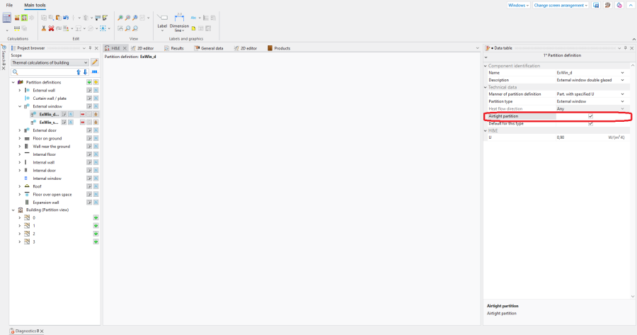
# Optionally, to exclude the infiltration of outside air caused by leaks, you can mark the definitions of partitions of the ''<IS_TS id=rsTypKonstrukcjiPrzegrodyOknoZewnetrzne/>'' and/or ''<IS_TS id=rsTypKonstrukcjiPrzegrodyDrzwiZewnetrzne/>'' type as ''<IS_TS id=strs_boolidISFKonstrukcjaPrzegrodyEN12831_Szczelna />'' in the ''<IS_TS id=DataEditorTable/>'' window. <br/>[[File:Airtight_partition.png|900 px|left|thumb|15. <IS_TS id=strs_boolidISFKonstrukcjaPrzegrodyEN12831_Szczelna />.]]<br clear="all"/> | |||
===Default partition definitions=== | ===Default partition definitions=== | ||
# Import definitions of thermal partitions from another .isproj file. If the current project requires the same definitions as those used in other projects, the earlier .isproj files may be used and partition definitions imported from them into the current project. <br/> {{#ev:youtube| | # Import definitions of thermal partitions from another .isproj file. If the current project requires the same definitions as those used in other projects, the earlier .isproj files may be used and partition definitions imported from them into the current project. <br/> {{#ev:youtube|LuDS1EsgQPI|900||||rel=0}} <br clear="all"/> | ||
# Create new definitions of thermal partitions in the project. Depending on the design needs and available data, three types of thermal partitions can be defined: | # Create new definitions of thermal partitions in the project. Depending on the design needs and available data, three types of thermal partitions can be defined: | ||
#* ''<IS_TS id=rsObliczeniowyTypKPrzegrodyGotowa/>'' | #* ''<IS_TS id=rsObliczeniowyTypKPrzegrodyGotowa/>'' | ||
#* ''<IS_TS id=rsObliczeniowyTypKPrzegrodyObliczana/>'' | #* ''<IS_TS id=rsObliczeniowyTypKPrzegrodyObliczana/>''. '''''Note:''''' The layers are defined in the direction from the icon [[File:Icon red thermometer.png |20 px]] - inner side of the ''<IS_TS id=rsPrzegroda/>'' (''<IS_TS id=iNameKonstrPomieszczenie/>''), to the icon [[File:Icon blue thermometer.png |20 px]] - outer side of the ''<IS_TS id=rsPrzegroda/>'':<br/>[[File:Inner outer side.png|900 px|left|thumb|16. The order of defining the <IS_TS id=rsPrzegroda/> layers.]]<br clear="all"/> | ||
#* ''<IS_TS id=rsObliczeniowyTypKPrzegrodyKompozytowa/>.''<br/> {{#ev:youtube| | #* ''<IS_TS id=rsObliczeniowyTypKPrzegrodyKompozytowa/>'' <br/><br/>{{#ev:youtube|3k9SNVamj2k|900||||rel=0}} <br clear="all"/> | ||
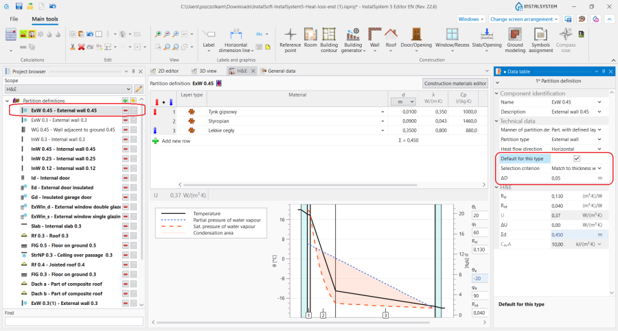
#In the ''<IS_TS id=DataEditorTable/>'' window of the individual ''<IS_TS id=sISFKonstrukcjaPrzegrody/>'' components specify default definitions by checking the ''<IS_TS id=DomyslnaDlaTegoTypu/>'' box and select ''<IS_TS id=strSposobAutomatycznegoPrzypisaniaDoPrzegrodyCaption/>'': ''<IS_TS id=strAnyThickness/>'' or ''<IS_TS id=strSuitToThicknessWithTolerance/>''. In the case of ''<IS_TS id=strSuitToThicknessWithTolerance/>'' the value must also be specified in the field: ''<IS_TS id=strDefPrzegrodyTolerancjaSymbol/>'' - ''<IS_TS id=strTolerancjaGrubosciDefinicjaPrzegrody/>''. All default definitions of thermal partitions are displayed in bold font in the ''<IS_TS id=rsPrzegrody/>'' list in the ''<IS_TS id=ProjectBrowser/>'' window. <br/>[[File:Default_partition.png|900 px|left|thumb| | # Frequently used building materials can be added to the ''<IS_TS id=Favorite/>'' folder by checking the star next to them. ''<br/> {{#ev:youtube|fc2ZVYL4ExY|900||||rel=0}} <br clear="all"/> | ||
# In the ''<IS_TS id=DataEditorTable/>'' window of the individual ''<IS_TS id=sISFKonstrukcjaPrzegrody/>'' components specify default definitions by checking the ''<IS_TS id=DomyslnaDlaTegoTypu/>'' box and select ''<IS_TS id=strSposobAutomatycznegoPrzypisaniaDoPrzegrodyCaption/>'': ''<IS_TS id=strAnyThickness/>'' or ''<IS_TS id=strSuitToThicknessWithTolerance/>''. In the case of ''<IS_TS id=strSuitToThicknessWithTolerance/>'' the value must also be specified in the field: ''<IS_TS id=strDefPrzegrodyTolerancjaSymbol/>'' - ''<IS_TS id=strTolerancjaGrubosciDefinicjaPrzegrody/>''. All default definitions of thermal partitions are displayed in bold font in the ''<IS_TS id=rsPrzegrody/>'' list in the ''<IS_TS id=ProjectBrowser/>'' window. <br/>[[File:Default_partition.png|900 px|left|thumb|17. Default <IS_TS id=sISFKonstrukcjaPrzegrody/>.]]<br clear="all"/> | |||
===Executing calculations and result veryfication=== | ===Executing calculations and result veryfication=== | ||
# Launch calculations by clicking the ''<IS_TS id=ObliczeniaCieplneBudynku/>'' icon [[File:Heat-loss-calculation-ikon.png|20 px|]] in the ''<IS_TS id=sObliczenie/>'' section on the ''<IS_TS id=NarzedziaGlowne/>'' bar and verify in the ''<IS_TS id=GraphicalEdit/>'' and ''<IS_TS id=View3D/>'' windows, for the enabled ''<IS_TS id=ScopeOZC_T_Short/>'' scope, whether the created thermal partitions have their definitions assigned to them.<br/> {{#ev:youtube|WbEPgWhCOUU|900||||rel=0}} <br clear="all"/> | # Launch calculations by clicking the ''<IS_TS id=ObliczeniaCieplneBudynku/>'' icon [[File:Heat-loss-calculation-ikon.png|20 px|]] in the ''<IS_TS id=sObliczenie/>'' section on the ''<IS_TS id=NarzedziaGlowne/>'' bar and verify in the ''<IS_TS id=GraphicalEdit/>'' and ''<IS_TS id=View3D/>'' windows, for the enabled ''<IS_TS id=ScopeOZC_T_Short/>'' scope, whether the created thermal partitions have their definitions assigned to them.<br/> {{#ev:youtube|WbEPgWhCOUU|900||||rel=0}} <br clear="all"/> | ||
# Review the created thermal partitions. If necessary, change the assigned default definition. The change may be done manually for a selected partition | # Review the created thermal partitions. If necessary, change the assigned default definition. The change may be done: | ||
# In the ''<IS_TS id=OZCModuleName/>'' window, for subsequent ''<IS_TS id=iNameKonstrPomieszczenie/>'' components, verify the determined values in the ''<IS_TS id=sENPrzegrodadU0_NaMostkiPNEN/>'' - ''<IS_TS id=strl_expidISFPrzegrodadU0_NaMostki/>'' field and, if necessary, modify them. <br/>[[File:Thermal_bridges.png|900 px|left|thumb| | #* manually for a selected partition | ||
#* by changing ''<IS_TS id=strSposobAutomatycznegoPrzypisaniaDoPrzegrodyCaption/>'', whereas if the ''<IS_TS id=strSposobAutomatycznegoPrzypisaniaDoPrzegrodyCaption/>'' is changed, it is necessary to run ''<IS_TS id=BuildingStructureCalculation/>'' again. <br/> {{#ev:youtube|aazZTZUPvaE|900||||rel=0}} <br clear="all"/> | |||
#* using the function: ''<IS_TS id= PrzypiszDoWszystkichPasujacych/>'' <br/> {{#ev:youtube|DqNpO2kL3mQ|900||||rel=0}} <br clear="all"/> | |||
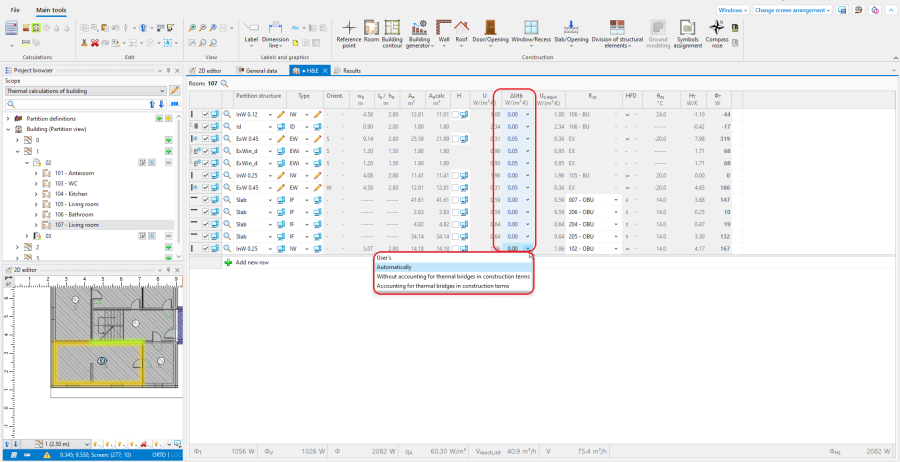
# In the ''<IS_TS id=OZCModuleName/>'' window, for subsequent ''<IS_TS id=iNameKonstrPomieszczenie/>'' components, verify the determined values in the ''<IS_TS id=sENPrzegrodadU0_NaMostkiPNEN/>'' - ''<IS_TS id=strl_expidISFPrzegrodadU0_NaMostki/>'' field and, if necessary, modify them. <br/>[[File:Thermal_bridges.png|900 px|left|thumb|18. <IS_TS id=strl_expidISFPrzegrodadU0_NaMostki/>.]]<br clear="all"/>{{Info}} [[Linear and point thermal bridges]].<br/><br/> | |||
# If changes in project have been made launch the the ''<IS_TS id=ObliczeniaCieplneBudynku/>'' calculations again and verify the obtained calculation results, in particular the following: | # If changes in project have been made launch the the ''<IS_TS id=ObliczeniaCieplneBudynku/>'' calculations again and verify the obtained calculation results, in particular the following: | ||
#* Error messages in the ''<IS_TS id=ErrorModuleTitle/>'' window for the ''<IS_TS id=ObliczeniaCieplneBudynku/>'' scope. | #* Error messages in the ''<IS_TS id=ErrorModuleTitle/>'' window for the ''<IS_TS id=ObliczeniaCieplneBudynku/>'' scope. | ||
#* Calculation results for the ''<IS_TS id=iNameKonstrPomieszczenie/>'' in the ''<IS_TS id=OZCModuleName/>'' window.<br/>[[File:Room_result.png|900 px|left|thumb| | #* Calculation results for the ''<IS_TS id=iNameKonstrPomieszczenie/>'' in the ''<IS_TS id=OZCModuleName/>'' window.<br/>[[File:Room_result.png|900 px|left|thumb|19. Calculation results for the <IS_TS id=iNameKonstrPomieszczenie/>.]]<br clear="all"/> | ||
#* Graphical representation of ventilation streams for mechanical ventilation in the ''<IS_TS id=GraphicalEdit/>'' window for the ''<IS_TS id=ScopeOZC_V_Short/>'' scope. <br/>[[File:Ventilation_flow.png|900 px|left|thumb| | #* Graphical representation of ventilation streams for mechanical ventilation in the ''<IS_TS id=GraphicalEdit/>'' window for the ''<IS_TS id=ScopeOZC_V_Short/>'' scope. <br/>[[File:Ventilation_flow.png|900 px|left|thumb|20. Graphical representation of ventilation stream flows.]]<br clear="all"/> | ||
#* Results displayed in hints and labels of ''<IS_TS id=iNameKonstrPomieszczenie/>'' components. | #* Results displayed in hints and labels of ''<IS_TS id=iNameKonstrPomieszczenie/>'' components. | ||
#* Tabulated results for the project presented in the ''<IS_TS id=ResultModuleTitle/>'' window. | #* Tabulated results for the project presented in the ''<IS_TS id=ResultModuleTitle/>'' window. | ||
===Presentation of an air flow=== | |||
# As part of the air flow presentation, the following are visualized: | |||
#* air flows between rooms within a ''<IS_TS id=iNameJednostkaBudynkuPlural/>'' (colorless arrow) | |||
#* air flow supplied from the outside (blue arrow) | |||
#* exhaust air flow (light purple arrow). </br>[[File: streams3.png |900 px|left|thumb|21. Presentation of ventilation stream flows.]]<br clear="all"/> | |||
# Individual air flows are not presented in situations where: | |||
#* definitions of partitions of the types ''<IS_TS id=rsTypKonstrukcjiPrzegrodyOknoZewnetrzne/>'', ''<IS_TS id=rsTypKonstrukcjiPrzegrodyOknoWewnetrzne/>'', ''<IS_TS id=rsTypKonstrukcjiPrzegrodyDrzwiZewnetrzne/>'', ''<IS_TS id=rsTypKonstrukcjiPrzegrodyDrzwiWewnetrzne/>'' have the ''<IS_TS id=strs_boolidISFKonstrukcjaPrzegrodyEN12831_Szczelna/>'' option set, | |||
#* in the building unit, there are no entered Vex\Vsu values in the rooms when the model for determining the amount of ventilation air and its flow is selected: ''<IS_TS id=rs_EN_WyborLiczeniaVinf_Kubatura/>'' or ''<IS_TS id=rs_EN_WyborLiczeniaVinf_DrzwiIOkna/>'', | |||
#* ''<IS_TS id=rsEN_TypWentylacji_Naturalna/>'' ventilation type is selected. </br>[[File: heat losses data.png |900 px|left|thumb|22. <IS_TS id=strl_enumidISFOZCDaneOgolneEN_TypWentylacji/>.]]<br clear="all"/> | |||
===Distribution of design thermal loads=== | ===Distribution of design thermal loads=== | ||
| Line 133: | Line 159: | ||
{|class="wikitable" style="width: 800px; margin: 0 auto;" | |||
!If you have any comments on this article, please send us a short message at ''info@instalsoft.com'' | |||
|} | |||
[[Category:InstalSystem 5]] | [[Category:InstalSystem 5]] | ||
| Line 138: | Line 168: | ||
<!-- Do not write text below this tag --> | <!-- Do not write text below this tag --> | ||
<br class="iwlinks"/>[[pl:Obliczanie projektowego obciążenia cieplnego pomieszczeń|Obliczanie projektowego obciążenia cieplnego pomieszczeń]][[ | <br class="iwlinks"/>[[pl:Obliczanie projektowego obciążenia cieplnego pomieszczeń|Obliczanie projektowego obciążenia cieplnego pomieszczeń]][[de:Berechnung der Auslegungsheizlast eines Raumes|Berechnung der Auslegungsheizlast eines Raumes]][[fa:محاسبه بار حرارتی طراحی|محاسبه بار حرارتی طراحی]][[zh-cn:房间热负荷的设计计算|房间热负荷的设计计算]][[bg:Изчисляване на проектен топлинен товар на помещения|Изчисляване на проектен топлинен товар на помещения]] | ||
Latest revision as of 23:02, 12 June 2026
| Product | InstalSystem 5 |
| Type of article | DESIGNING LESSON |
| Source for translation | 2026-02-20 |
Scope of lesson
The article presents the procedure for preparing data for calculating the design heat load of rooms with the use of standard packages.
Modules and program configuration
- InstalSystem 5 package with the module:
- (Heat loss)
The videos present the topics described in this article, but they aren’t a recording of this lesson.
Project file
The project file used in this lesson: Design heat load in residental building (example for the lesson).
Inital state
The project includes building structure (storeys, building units, rooms, graphical partitions) and starting package of standards.
For more information, see: Preparation of building structure.
Another project file contains definitions of partitions to be imported.
Steps to perform
Preparation of building structure
For more information, see: Preparation of building structure - Complete building structure.
Preparation of building structure introduces graphical partitions that form structural components of the building, i.e. , , , , , etc.
At this stage the project can also be provided with a ground model. For more information, see: Ground modeling.
Completion and verification of the building structure
- Optionally, if it is necessary, make manual modifications to the building structure, i.e. reassign selected rooms to , create new , etc.
For more information, see: Editing data of Building units. - tab - enable project scope: .

1. . - Execute .

Verification of thermal partition model
During the automatic thermal partitions are created based on structural elements and automatically recognized . Thermal partitions are of primary importance in further , therefore, they require verification, especially in cases of complex geometry (multi-pitched , ).
A thermal partition is a logic component which is a fragment of a graphical partition within a single room. It is created automatically and is used in the calculation and presentation of heat losses due to transmission across a partition within a single room.
Attention! No thermal partition is formed between type components separated by a with a thickness of 0.
Attention! The necessary condition for precise creation of thermal partitions is the correct recognition of the . For more information, see: Preparation of building structure - Complete building structure.
Attention! After each correction to the , it is necessary to restart the .
- In the window enable the editing scope and check that the created model of thermal partitions is complete. To make the view clearer select the option for the editing scope.
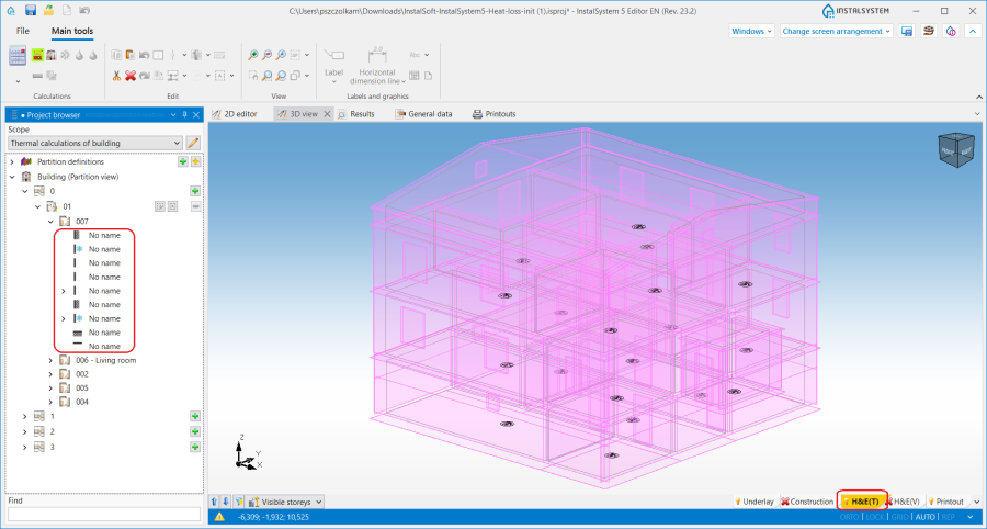
2. Model of thermal partitions. - Use the function for more precise verification of the created thermal model.

3.. - The must be launched after any modification of the to generate the model of thermal partitions. If, upon verification, the model proves to be incomplete or faulty, the must be provided with the required structural components, and must be performed again.
- If the component was used in the project, and the is sunk below ground level, at this stage the border is displayed between the and partition types which is demarcated by the shape of the ground outline around the building.
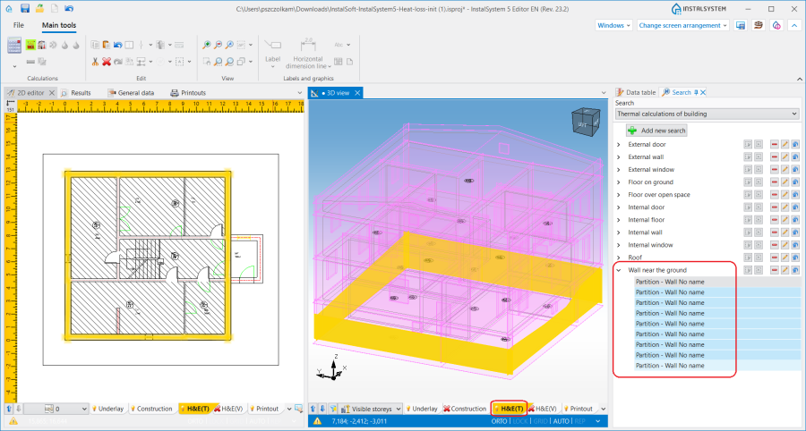
4. and types of partition demarcated by the ground line.


For more information, see: Checklist for verifying thermal partitions.
In order to make the completion and verification of the thermal partition model straightforward and satisfactory, please familiarize with the following articles:
- Preparation of building structure - Complete building structure
- Preparation of building structure - Roof modeling
- Preparation of building structure - Roof modeling - Creation of dormers
- How to eliminate diagnostic messages regarding building structure
- The most common situations in complex geometry - quick solutions
If, after completing the verification steps, you still have doubts about the thermal partition model, send a request from InstalSystem 5 Manager or use the Contact with the support team.
Default data setting for the project
- tab - select appropriate Standards package and set important parameters for thermal calculations (dispaly of some data in the tab is determined by selections made in the field):
- . For more information, see: Linear and point thermal bridges
- .
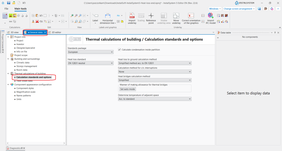
5. .

Editing building and surroundings data
- tab - specify the location of the building by making selections in the list of fields:
- .
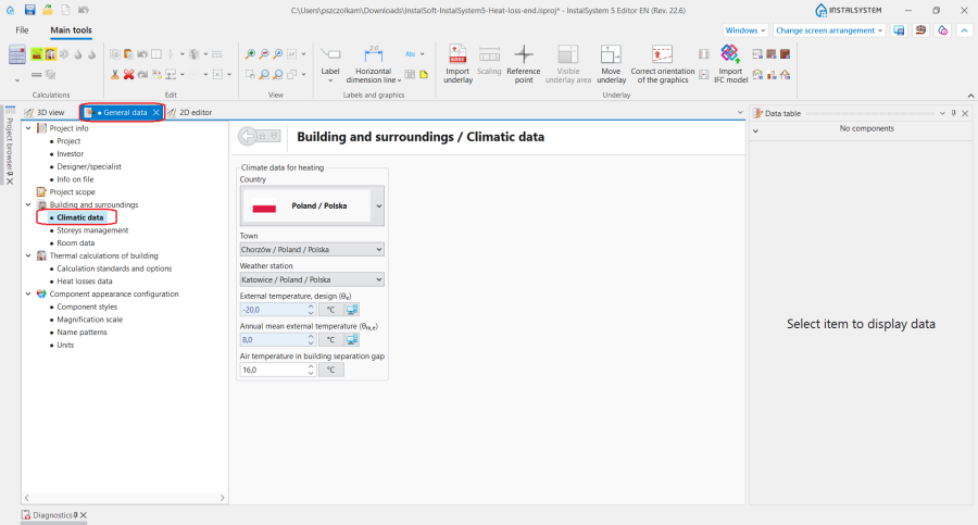
6. .
- Every location is assigned automatically to a weather station for which the climatic database specifies the required values, e.g.:
- .
- tab - enter the value in the field.
- tab - if necessary, in the window, component , modify .
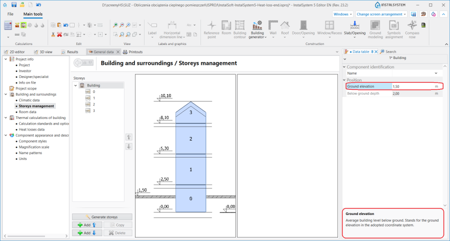
7. of a . - tab - specify the important parameters of the building for in the fields displayed in the form. The display of some data in the tab depends on the selection made in the field on the tab.
Data fields displaying red question marks, if set in the mode , will be filled automatically after performing the first calculations. The following data are available in the form, e.g.:
- Data on building structure:
- .
- :

8. . - .
- Data on building structure:
- tab - specify important room data:
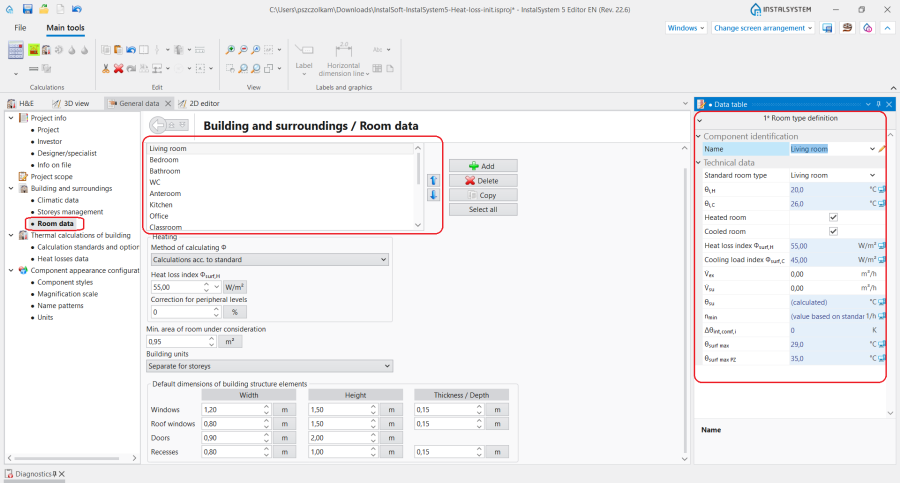
9. .
- - the field list provides default components. The data and calculation parameters that can be modified or specified for the selected room types are displayed in the window after the room type is checked in the field list.
Data entered for the first room in the list become the default data for every placed in the project. If necessary, the order of components in the list can be changed using the arrows. For each selected its can be changed in the window; it is also possible to enter user-defined room types. - - when working with the scope, check the option. The selection in the list is distributed to all components placed in the project and it can be modified manually in the window for the individual compnents.
- - set or as required.
For more information, see: Editing data of Building units.
- - the field list provides default components. The data and calculation parameters that can be modified or specified for the selected room types are displayed in the window after the room type is checked in the field list.


Editing room, partition and building unit data
- Review the building structure in the window for the scope. If necessary, in the window change the for selected components to a type other than the default and modify the - in components of non-uniform temperatures.

10. - window. - Optionally, modify the assignment of components to the . The change can be made in the field in the window for a selected or in the window by dragging the selected in the building structure to the target .
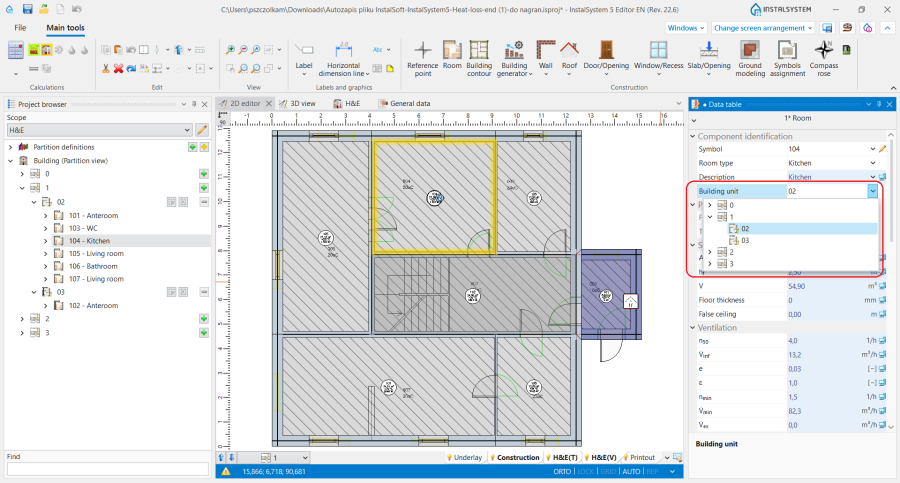
11. Changing the building unit. - Review and, if necessary, specify or modify the data. The display of some data of the depends on the selection made in the field in the tab:
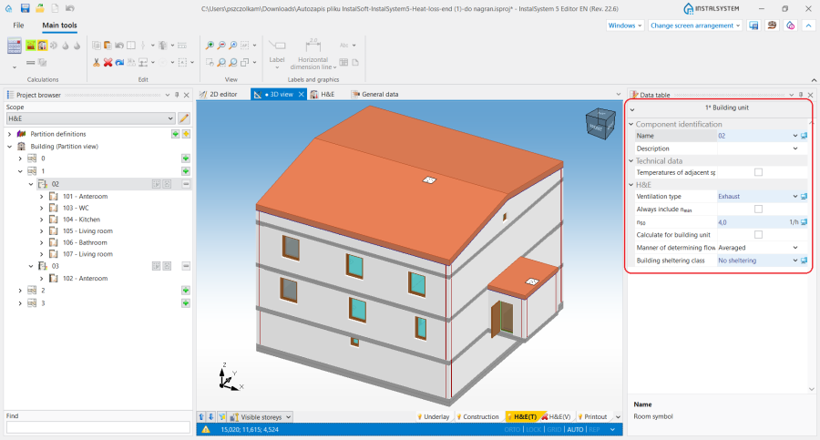
12. Building unit - data table.
- -
- -
- Verify and, if necessary, modify the state of the heated partitions (integrated with heating floors or heating walls). The settings in the field can be group-verified in the window for the selected element.

13. . - Optionally, if the actual building structure cannot be fully modelled in the program, in the window, for the selected , add manually Table partitions by clicking . For each partition specify , or and select .
Note: Table partitions can be added when:- the physical shape of the partition is too complicated,
- according to the requirements of the project, the priority is the correct , rather than precise drawing from an architectural point of view.
- Review and, if necessary, change the value of () for the when the is selected.

14. Changing the . - Optionally, to exclude the infiltration of outside air caused by leaks, you can mark the definitions of partitions of the and/or type as in the window.
15. .


Default partition definitions
- Import definitions of thermal partitions from another .isproj file. If the current project requires the same definitions as those used in other projects, the earlier .isproj files may be used and partition definitions imported from them into the current project.
- Create new definitions of thermal partitions in the project. Depending on the design needs and available data, three types of thermal partitions can be defined:
- . Note: The layers are defined in the direction from the icon
 - inner side of the (), to the icon
  - outer side of the :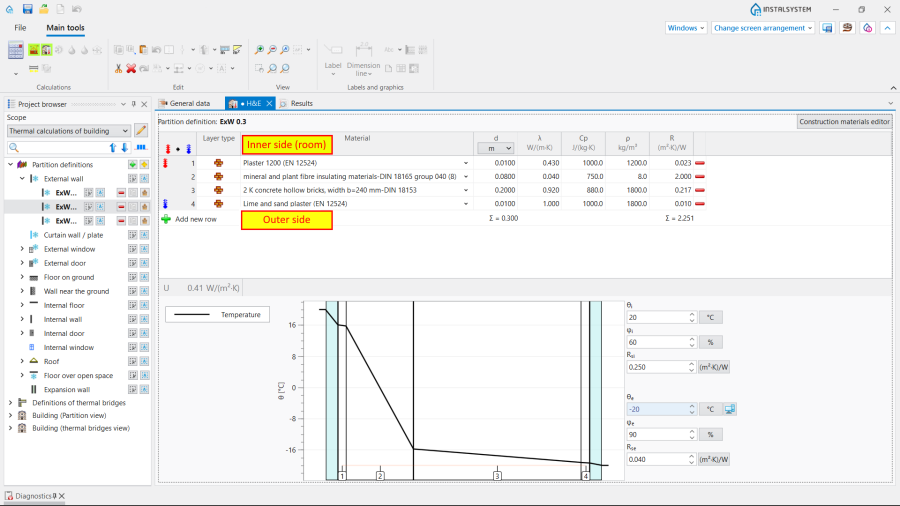
16. The order of defining the layers. -
- Frequently used building materials can be added to the folder by checking the star next to them.
- In the window of the individual components specify default definitions by checking the box and select : or . In the case of the value must also be specified in the field: - . All default definitions of thermal partitions are displayed in bold font in the list in the window.
17. Default .


Executing calculations and result veryfication
- Launch calculations by clicking the icon
 in the section on the bar and verify in the and windows, for the enabled scope, whether the created thermal partitions have their definitions assigned to them.
- Review the created thermal partitions. If necessary, change the assigned default definition. The change may be done:
- manually for a selected partition
- by changing , whereas if the is changed, it is necessary to run again.
- using the function:
- In the window, for subsequent components, verify the determined values in the - field and, if necessary, modify them.
18. .
For more information, see: Linear and point thermal bridges. - If changes in project have been made launch the the calculations again and verify the obtained calculation results, in particular the following:
- Error messages in the window for the scope.
- Calculation results for the in the window.
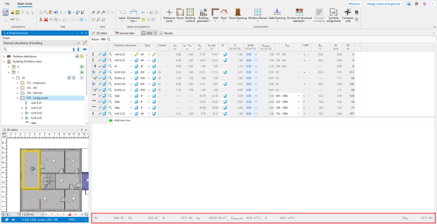
19. Calculation results for the . - Graphical representation of ventilation streams for mechanical ventilation in the window for the scope.
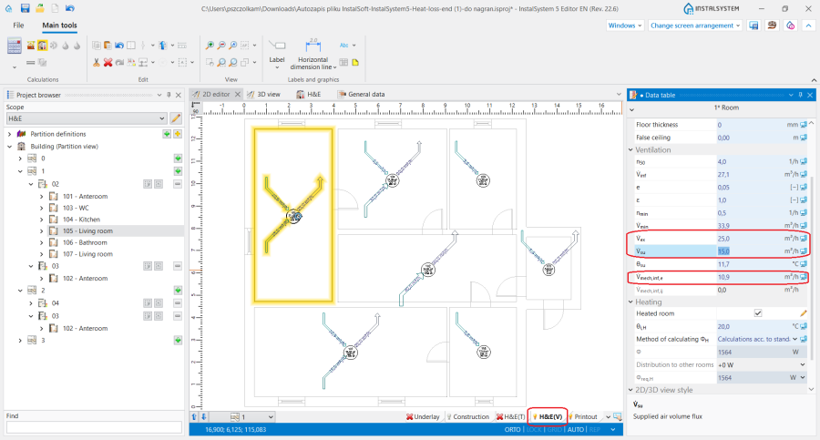
20. Graphical representation of ventilation stream flows. - Results displayed in hints and labels of components.
- Tabulated results for the project presented in the window.


Presentation of an air flow
- As part of the air flow presentation, the following are visualized:
- air flows between rooms within a (colorless arrow)
- air flow supplied from the outside (blue arrow)
- exhaust air flow (light purple arrow).
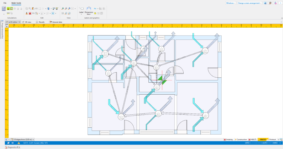
21. Presentation of ventilation stream flows.
- Individual air flows are not presented in situations where:
- definitions of partitions of the types , , , have the option set,
- in the building unit, there are no entered Vex\Vsu values in the rooms when the model for determining the amount of ventilation air and its flow is selected: or ,
- ventilation type is selected.
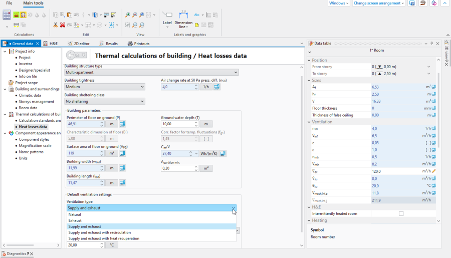
22. .


Distribution of design thermal loads
- Enter the heat distribution data, if there is a in the project the thermal load of which is to be distributed to adjacent rooms. Data editing can be done in the window for the in the editor.
- Select the method of calculating heat distribution:
- - enables manual selection of adjacent rooms from the list of all rooms, and specifying its percentage to the coverage of heat losses of the selected room.
- - enables selection of adjacent rooms from the list of all rooms, while its percentage to the coverage of heat losses of the selected room is determined automatically, in proportion to the calculated heat losses.
- - adjacent rooms and their percentage to the coverage of heat losses of the selected room is determined automatically, in proportion to the calculated heat losses, taking into account partitions of the or type present in the partitions separating the selected room from adjacent rooms.
- The field displays the value of the power distributed:
- For components that deliver energy to adjacent rooms the value of the power delivered is preceded by a minus sign.
- For components that acquire energy from adjacent rooms the value of the power is preceded by a plus sign.
- For the : option the value of power for the 'energy acquirer' is displayed after the editor window is closed.
- Energy can only be transmitted between components that are separated by an or an .
- Run again and verify the results obtained.
Prepare drawing for printing/export
For more information, see: Presentation of the calculations result.
| If you have any comments on this article, please send us a short message at info@instalsoft.com |
|---|