Preparation of building structure - Roof modeling
| Product | InstalSystem 5 |
| Type of article | FUNCTION AND TOOL |
| Source for translation | 2024-11-17 |
Description
The article describes the possibilities of preparing various kinds of Roof constructions. The detailed description of the creation of the basic design cases of roofs could be found here: Basic design cases.
Functions and tools related to the creation or modification of the Roof structure and related elements are the following:
- Construction scope, Roof tab:
- Roof,
- Add roof edge,
- Dormer, For more information, see: Creation of dormers.
- Join roofs,
- Opening in roof;
- Construction scope, Window/Recess tab:
- Roof window;
- Underlay scope, Interpret from IFC file tab:
- Creates roofs from an IFC file,
- Creates windows, doors, and wall openings from an IFC file (to create Roof window);
- Operations related to the creation of Roof during preparation of Building structure:
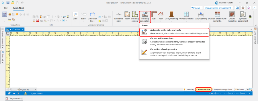
- Building generator - Automatic walls, slabs and roofs,
- Convert to roof (right mouse button context menu),
- Trim slab (by roof element).
Attention! In order to view the effects of any changes made during editing it is necessary to invoke Computation of building structure .
For more information, see: Preparation of building structure.
Location in the program
Construction scope
Icons of tools and functions related to the creation of Roof are accessible in the 2D editor and partly in the 3D view window on the Main tools bar, section Construction when Construction editing is enabled.


Underlay scope
Icons of tools and functions related to the creation of Roof and its elements from the IFC file are accessible in 2D editor and 3D view windows on the Main tools bar, section Underlay when Underlay editing is enabled, Interpret from IFC file tab.

Related operations
- Automatic walls, slabs and roofs operation is available in 2D editor and 3D view windows on the Main tools bar, section Construction when Construction editing is enabled, Building generator tab. Allows to automatically generate Roof on the basis of previously created Rooms and Building contour.
4. Automatic walls, slabs and roofs. - Convert to roof operation is available in 2D editor and 3D view windows in the right mouse button context menu. Allows to convert Slab element into Roof.

5. Convert to roof. - Trim slab (by roof element) function is accessible in 2D editor and 3D view windows on the Main tools bar, section Construction when Construction editing is enabled, Slab/Opening tab.

6. Trim slab (by roof element).


Computation of building structure
- Computation of building structure is available on Main tools bar, section Calculations.

7. Computation of building structure .

Example of use
The steps to be performed to create Roof will depend on the format of the file used like an Underlay.
Working with DWG / DXF / PDF files
There are two ways to create Roof in case the files of dwg, dxf of pdf formats are used:
- Manual creation. Use the tools available in the program and listed above.
- Automatic creation based on the Automatic walls, slabs and roofs function. In this case the program will generate the flat Roof in accordance with the data set in the General data window, Storeys management tab for the last Storey. The roof edges with the corresponding elevations can be added manually.
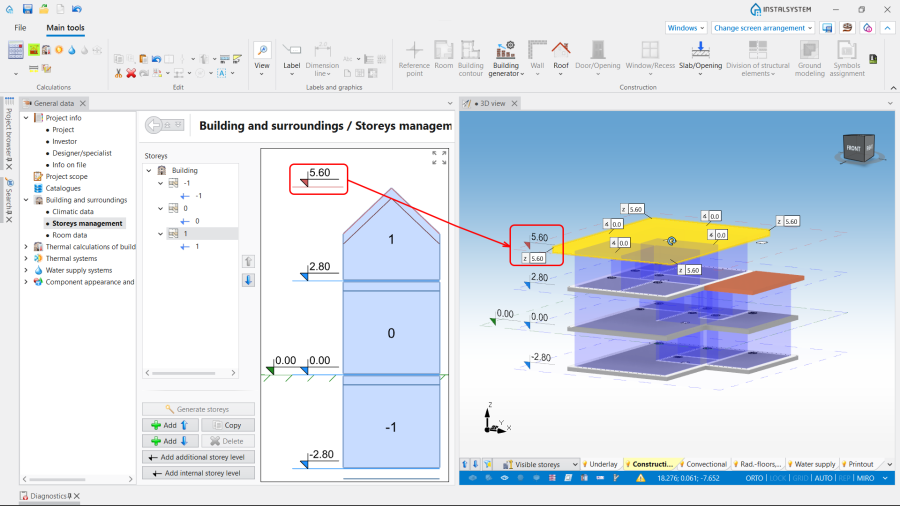
8. Storeys management.

Attention! For user convenience, the program provides the opportunity to use two underlays - the plan view of the last storey and the roof plan view - on the same worksheet.
In order to be able to create correct Building structure using both underlayers, the following steps should be carried out:
- Make Import underlay with roof plan view on the worksheet with imported plan view Underlay. For more information, see: Import underlay files;
- Scale the Underlay using the Length measurement and the Scaling functions;
- Move underlay to make the exact positioning of the underlays in relation to each other.
Automatic walls, slabs and roofs
This is the way to Generate walls, slabs and roofs from rooms and building contour.
For more information, see: Building generator.
Convert to roof
Building generator allows to create only one roof in a building. The rooms not belonging to the last Storey are covered from above with Ceiling slabs. If the building construction foresees the presence of a Roof element in such a place, the Slab can be easily converted into a Roof using the Convert to roof function by previously dividing the Slab with the Division of structural elements operations.
Add roof edge
The Roof is the only element in the program that can create not only a strictly horizontal (or vertical) structural Partition. Its further modelling is performed using the Add roof edge function, which Inserts edges that allow to divide a roof into many slopes with any angle. After the Computation of building structure is performed, the modelled Roof automatically cuts vertical partitions in the project. Note: During the creation of roof edges, they may turn red. This means that these edges cannot be realized. In such a case, the correction of elevations or slopes is required. For more information, see: How to eliminate common mistakes and diagnostic messages regarding roof modeling.
Trim slab (by roof element) used for the multi-storey Roof modeling
There are situations when the Roof crosses 2 or more Slab elements. In this case there is no necessity to correct the Slab in accordance with the shape of the Roof manually. The usage of the function Trim slab (by roof element) allows to trim the outer part of the Slab automatically.
Creation of a loggia
For more information, see: Creation of a loggia.
Working with IFC files
The program automatically interprets Roof elements created in IFC format files.

For more information, see: Interpretation of roofs.
Roof window
The Roof window icon is located on the Construction section, Window/Recess tab.
The following guidelines should be followed when positioning this element:
- The Roof window is placed on an already finished and calculated Roof without any Errors,
- After inserting the Roof window, there is no need to cut holes for the windows. The program will automatically update the partition model after the Computation of building structure have been carried out;
- Avoid inserting Roof window at the edges of the Roof. If this design situation does exist, divide the Roof window into 2 elements and move them appropriately close to each other.
Roof in the aspect of designed Drainage systems
The Drainage systems module(s) does not require a complete Building structure. However, the presence of a Roof element means that the Position of designed Vent pipe is based on the model and the Roof edge and correctly adapted to the available Roof slopes. The absence of the Roof element in the project causes the Elevation of the Vent pipe to be equal to the value of the Elevation of roof top taken from the Storeys management.
Additional information
The general theory of roof modelling is briefly summarized here: Roof modeling rules in InstalSystem-5.
| If you have any comments on this article, please send us a short message at info@instalsoft.com. |
|---|