Designing gravity sanitary sewage installations
| Product | InstalSystem 5 |
| Type of article | DESIGNING LESSON |
| Source for translation | 2025-11-20 |
Scope of lesson
This article presents the basic design path for the internal gravity sanitary sewage installation between the sanitary fixtures and the building outlet.
Modules and program configuration
- InstalSystem 5 with the module:
- Domestic wastewater gravity systems
The videos present the topics described in this article, but they aren’t a recording of this lesson.
Project file
The project file used in this lesson: Gravity sewage instalation in multifamily building (example for the lesson).
Initial state
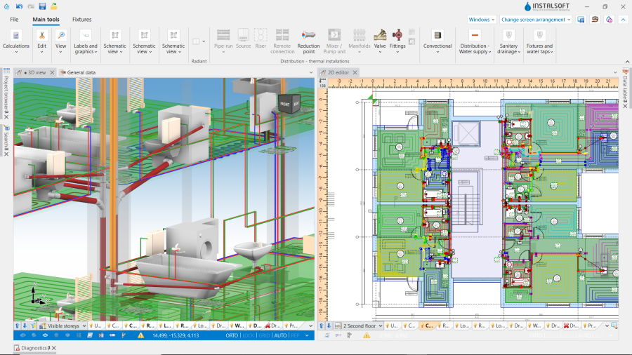
The project contains complete default data configured in the template file. The building structure has been elaborated on the basis of DWG layouts. The first floor accommodates the Fixtures.
Steps to perform
Opening the project file
- When creating a new design, select from the list the template that contains the default data for the drainage system,
- (or): upload an existing building structure file - minimum content is correct ordinates and slab thicknesses. If the design was created with a configuration that did not include the drainage system, import the drainage system general data from the appropriate template.
For more information, see: Template files
Editing the general project data
Enable Sanitary drainage systems scope. Verify data that affect significantly the geometry of the drainage system, unique to each project:
- Default depth of waste outlet relative to zero level of the project, where the status "(size)" means - let the program determine the highest value achieving required gradients,
- floor thickness specifications (layers placed on the floor slab) on individual storeys - ATTENTION! this may affect previously completed or planned designs of other systems in this file. Drainage fixtures are positioned on the floor or at a predetermined distance from the floor surface.
Further adjustment of the general data may be necessary when work is started on a file created without a drainage module and without a dedicated design template:
- In the Sanitary drainage systems tab specify:
- Calculation standards and options:
- In the Calculation standard tab select the one appropriate for the market region,
- Building type,
- Specify mimimum gradients in accordance with design requirements and applicable regulations,
- Indicate the default direction for the Method of conducting of branches,
- For the selected direction define the default value of the Distance from the floor of the connection points to the stack - which will be applied on all storeys in the project, and which then can be individually modified on selected storeys,
- Default pipe-run fill ratio.
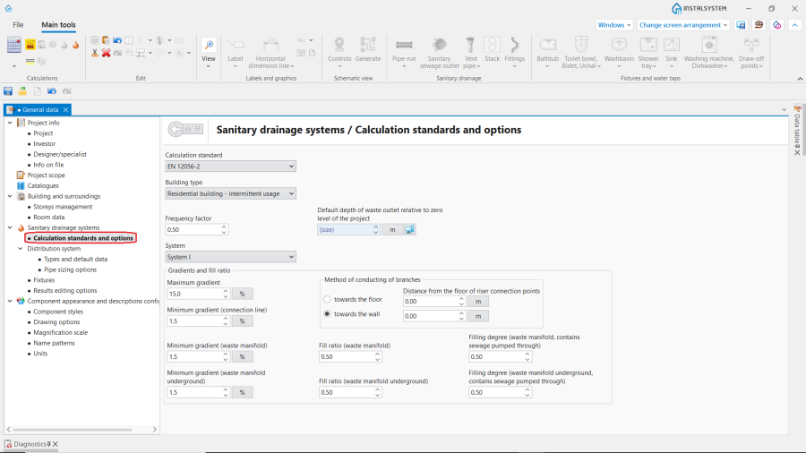
1. Calculation standards and options.
- Calculation standards and options:

- In the Distribution system tab specify Types and default data for each component with regard to,
- Default pipe type: Drainage / Ventilation conduit for the various pipe-run locations,
- Default methods of implementation of connections - the picklists depend on the content of default pipe catalogues for the given location,
- Default types: Other components.

2. Types and default data.
- In the Fixtures table assign data with regard to:
- For each Fixture specify Default type and Type of water receptor. Optionally, Default connection system and Default frame,
- Connection system of other sanitary appliances - common selection for the remianing fixture types.
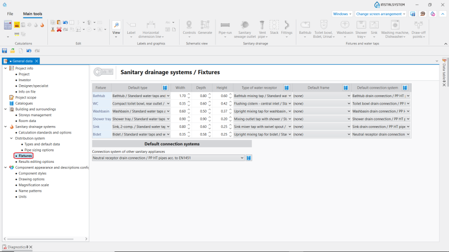
3. Fixtures.
- Editing data in the Storeys management project section for storeys with a drainage network,
- Determine the required value of ΔHpipe-run,,VS - Default distance of drainage ventilation manifold from the ceiling,
- Point of passage of the stack to the collector - set for the storey on which the drainage network is drawn. Select the necessary variant. For the items "At given distance beneath upper slab of the storey" and "At given distance beneath lower slab of the storey" specify Distance of the passage point stack to the collector. The items "Beneath lower slab of the storey" and "At given distance beneath lower slab of the storey" are appropriate for cases, where the drainage network is below the slab of the lowest storey, e.g. in the ground below the building,
- Method of conducting of branches - change if on a given storey the value is different from that set out in the general data above,
- Distance from the floor of the connection points to the stack - negative values mean placing junctions on risers in plumbing shafts within a floor or ceiling slab, which may be necessary to maintain proper gradients from low-placed fixture outlets.
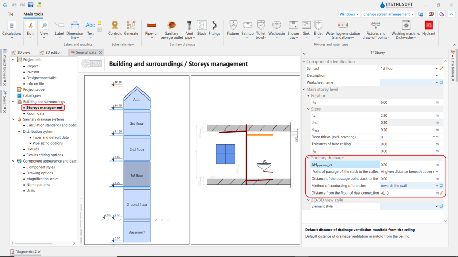
4. Storeys management. Sanitary drainage settings.


Editing the installation and its data
Editing the installation structure
- Insert sanitary appliances, if these were not included in the file, e.g. from a previously completed design of water supply system. For more information, see: Editing sanitary installation.
In the case of necessity to use sanitary appliances with Frame, this can be indicated in the General project data for each particular Fixture type or directly on the drawing for each particular Fixture:- Сheck the box Frame in the Data table window for the Fixture,
- Specify the Type of the Frame,
- For the Frame with embedded outflow bend set the Rotation angle of outflow bend.

5. Inserting Frame.
- Insert Stack elements and complete their essential data in the Data table window:
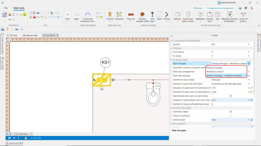
- Depending on the purpose of the Stack element, declare the proper type in the Pipe-run types field. Define additional parameters for double stacks (Sanitary drainage + Ventilation conduit): Pipes axes distance, Automatic creation of parallel ventilation checkbox selection.
- In the Element on top of stack field, define the way in which the pipe-run at the last storey for the Stack element finishes:
- For the waste stack, it is necessary to choose the vent element (e.g. Vent pipe), leaving the None option selected means that a vent manifold should be added in future,
- The chosen position None - not ventilated stack allows to create a relatively short Stack that does not require ventilation and can connect only two adjacent storeys,

6. Element on top of stack. - The vent Stack should be ended with a vent element, or it should be connected to the drainage stack.
- In the Position section, declare the range of storeys of the Stack.
- Perform the necessary steps to create Stack element with a deviation (different XY coordinates on diferrent storeys). For more information, see: Creating Drainage stacks with deviation.
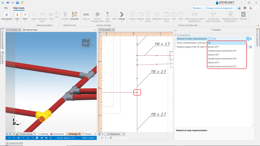
- (Optionally) Declare the default Method of node implementation for the particular Stack in section Junctions of branches in the Data table window. This field defines the fittings used for the connections of the branches from the appliances (single and collective) to the stack.
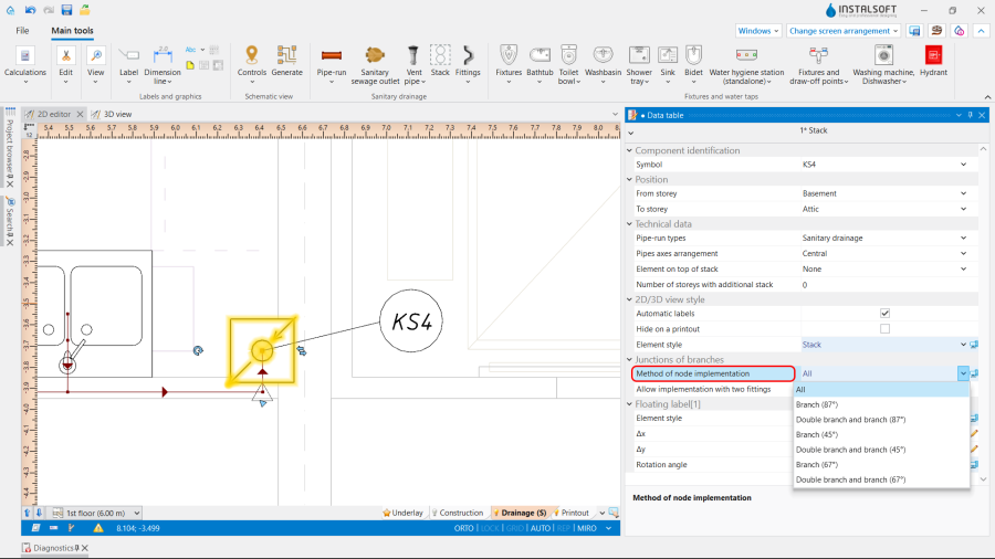
7. Method of node implementation.
- In many cases of Bypass ventilation the internal structure of stacks should be changed. This is achieved by modifying stack data: types of pipes inside, declaration of elements on the top, declaration of internal connections, etc. The type of the stack is indicated in the Data table.
8. Pipe-run types.
All necessary points should be specified. Some geometrical data (distances between internal connections) have default values, but these may not fit all cases and often require manual correction after observing the 3D model.
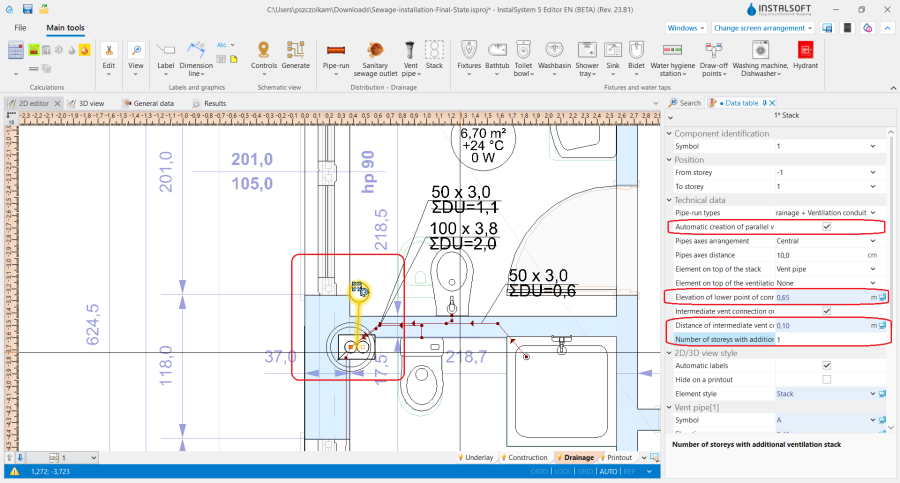
For theStack elements with bypass ventilation (with selected checkbox Automatic creation of parallel ventilation in the Data table element window), verify and, if needed, change the following parameters:- Select the Generate intermediate ventilation connections checkbox,
- Set the value in the Distance of intermediate vent conn. from ceiling field,
- (Optional) change the value in the Elevation of lower conn. of vent stack to drain stack field and the elevation of the upper connection of vent. and drainage Stack,
- (Optional) declare a number > 0 in the Number of storeys with additional stack field (counting from the lowest storey).
9. Automatic creation of parallel ventilation.
The program provides several schemes of bypass ventilation. Please note, that all changes inside the stack can be achieved only by changing stack data (no graphical edition possible). After drawing and connecting a ventilation pipe-run to a sewage pipe-run, manual correction of the elevations may be necessary.
Sample files with different schemes of bypass ventilation you can find in the article Sewage installations - Bypass ventilation.
- Note: If to edit all of the above data before inserting the Stack, the accepted parameters will temporarily become default values and will initialize when the Stack element is selected again.
- Insert the Sanitary sewage outlet and verify its position in the model,
- Connect the appliances with the Stack using the Pipe-run components. ATTENTION! In the drainage system this component always consists of a single section. If, for perpendicular connections, other than 90-degree branch fittings are needed, they should be declared in the General data window in the Types and default data tab in the Default methods of implementation of connections section, and connections of Gravity sanitary drainage pipe-run elements should be drawn as perpendicular (do not use "chamfering" in the plan view).
- In cases where a Pipe-run should be connected on an elevation different than the default, change Method of declaring the point of connection to the stack to:
- User defined - the required value of Distance from the floor of connection to the stack is to be set manually;
- Elevation determined from the gradient of pipe-run - the required value of Distance from the floor of connection to the stack will be determined based on the gradient of the Pipe-run.
- Note: We recommend to define the value of Distance from the floor of the connection points to the stack to be used by default in the General data window for the usually lowest connection (e.g. for a Toilet bowl) and use another methods for the others.

10. Method of declaring the point of connection to the stack. - If Special Inlet Fitting is used, follow the steps described in Applying Special Inlet Fitting in the sewage installation with VBF.
- On the storey where Sanitary sewage outlet is placed, connect it with the Stack, to form the sewer collector network. The elevation of the beginning of this network is adjusted to the value of Point of passage of the stack to the collector. If the elevation of Sanitary sewage outlet has been set manually, and is lower than the minimum required to achieve the gradients, the program may generate additional vertical pipe-runs.
- If the layout of the rooms on each storey is the same, the following steps are recommended to avoid further multiple and identical adjustments:
- Сreate an installation according to the guidelines given above. In doing so, locate the sanitary appliances and make the connections on one, typical storey only;
- Use the function Check connections (Shortcut: Shift + F2) to verify the correctness of the created installation;
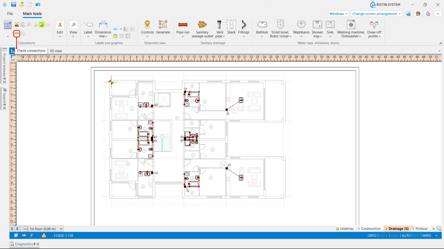
11. Check connections. - Run calculations;

12. Run calculations. - Check visual correctness of the installation using 3D-model. Make manual improvements, if necessary:
- Minimum gradient and Maximum gradient,
- Elevation of first node, Elevation of second node or Real gradient,
- Method of declaring the point of connection to the stack.
Note: After each improvement, a recalculation of the project is required to see the result.
- After expected model of the typical storey is obtained and calculated, copy repetitive parts of the installation to other storeys using Copy selected elements to the storey above or Copy selected elements to multiple storeys function.
- Insert necessary Fittings in the 2D editor or on the 3D view, these may be elements such as Bypass bend, Wastewater backflow preventer, Sewer inspection and similiar.
Set the Type from available catalogues and, if necessary, adjust the Rotation angle.
Note: If it is necessary to insert the same Fittings into multiple pipe-runs, select Pipe-run elements in the 2D editor or on the 3D view and use the function Insert to all selected components. The Fittings elements are inserted in the centre of each Pipe-run. Their location can be corrected by moving them with the use of mouse when they are selected after insertion or after they have been reselected.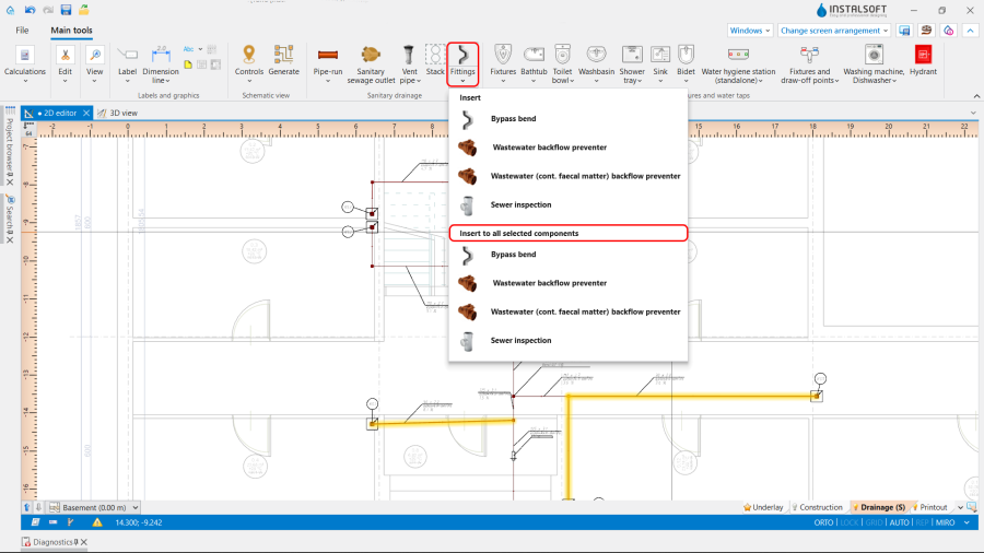
13. Insert to all selected components.


Verifying the correctness of the installation structure.
- Verify the correctness of the connections of the installation components using the Check connections function (Shortcut: Shift + F2).
Note: To avoid unnecessary short vertical pipe-runs, increase the Maximum gradient of the adjacent horizontal pipe-run.
- Verify the correctness of the installation structure and detect collisions with other systems using the 3D view. If necessary, enable the view of other editing scopes, in such case it is advisable to turn off the display of walls.
14. Verifying the correctness of the drainage installation structure using the 3D view. - Verify provisionally the vertical routing of pipe-runs in the model (calculations may alter this).
- Specify, if necessary: the elevations of the ends of the pipe-runs (paying attention to constraints resulting from their connection to other components), the actual gradients of pipe-runs.

ATTENTION! Following such changes, verification must be repeated.
Editing installation components data
- Verify and adjust the drainage-specific data of the appliances (DU, outlet diameter),
- If necessary, verify and change pipe-run data to values other than default (pipe type, diameter, minimum and maximum gradient),
- (Optional) If needed, change the way of realizing chosen pipe-run's nodes to other than the default, set in general data. It is possible in the Data table window for the Junction element.
15. Change of pipe-run node realization.
The following functions can be used to ergonomically select multiple nodes in a Stack:- Select stack components - is available in 2D editor and 3D view windows in the right mouse button context menu.
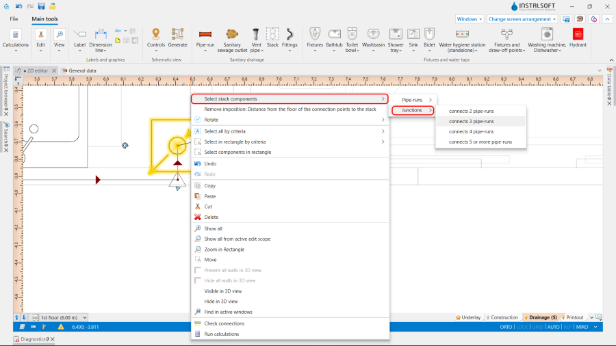
16. Select stack components. - Add new search in the Search window. For more information, see: Search window.

17. Search window.
- Select stack components - is available in 2D editor and 3D view windows in the right mouse button context menu.


Running the calculations
- If no errors are found during verification, start the calculation of the Drainage systems by clicking
 in the Calculations section of the toolbar. The calculations finally determine the vertical routing of the pipe-runs.
 - After the calculations, it is possible to correct manually the vertical passage of pipe-runs in the following way:
- imposing proper values in the Data table window for the Gravity sanitary drainage pipe-run element in the following fields: Real gradient, Elevation of first node, Elevation of second node,
- dividing the chosen pipe-runs into parts and modifying their data.
It is recommended to implement such changes gradually and to observe their influence upon the system, as the change in one node after calculations may have a significant impact on positioning of its greater part.
- Note: Defining the vertical passage of pipe-runs, the program does not exceed the value imposed in the Maximum gradient field in the General data window in the Calculation standards and options tab. This value is also automatically propagated to data of all pipe-runs. In case a difference of ordinates between the end of the calculated pipe-run and another pipe-run or a sewage outlet occurs, an additional vertical pipe-run is generated. To avoid it, allow for a greater gradient, by augmenting individually for each pipe-run a new value in the Maximum gradient field of the Data table and then recalculating the project.
Verification of results
- After calculations, the system layout should be verified visually by means of the 3D view.
- If the calculations end with at least one error, the layout may be unreliable
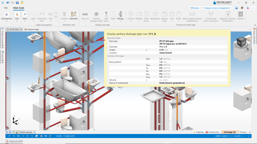
- The sized diameters of the pipe-runs and fittings can be verified directly in the drawings.
18. Visual verification in the 3D view window. - If a catalogue with visualisation of fittings (like tees, bends etc.) is used in the project, it can helpful in assessing the correctness of fittings selection and sizing for pipe-run nodes (junctions). To do so, node visualisation should be turned on in the General data window, on the Drawing options tab, or using the icon of the Installation elements' visibility directly in the 3D view.
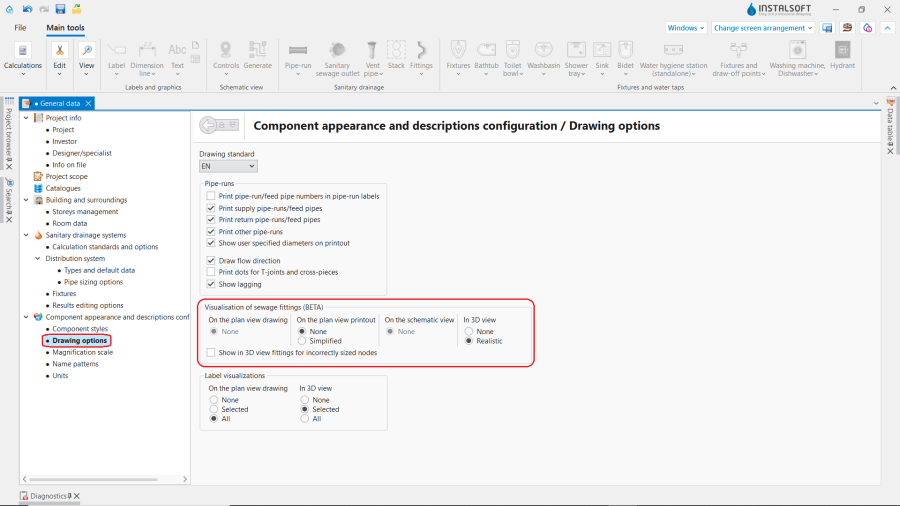
19. Visualization of sewage fittings.
Note: By default, only the nodes with correctly selected fittings, for which there are no warnings in the Diagnostics window, are visualised. Visualisation of the nodes having angle tolerance warnings may be enabled on request, and they will be drawn in a different colour.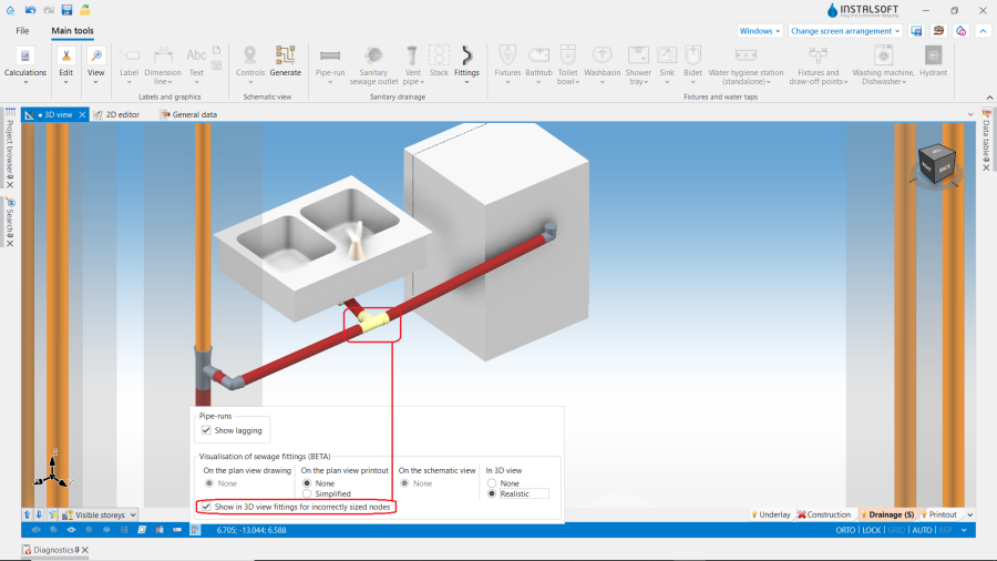
20. Show in 3D view fittings for incorrectly sized nodes. - Other forms of presentation of calculation results are: component labels and tables of results For more information, see: Presentation of the calculations result
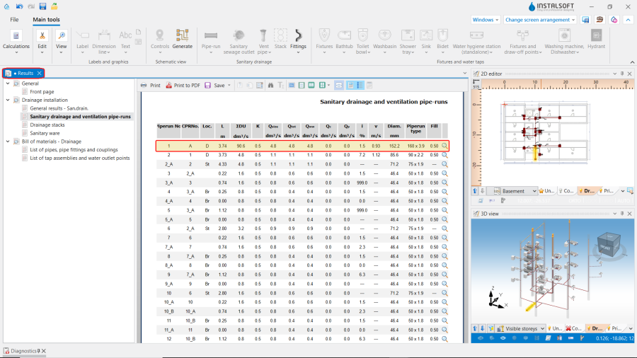
21. List of pipes, pipe fittings and couplings.


Incorrect gradient value %s %
In order to finish the calculations regardless of occurrence "Incorrect gradient value %s %" Errors, check ON the checkbox Tolerable value of gradient for branches in the General data window / Calculation standards and options section and correct the value if necessary:
Generating schematic views
Further steps like in Automatically generate schematic views.
Preparing drawings for export/printing
- To have the results for pipe-runs and installation nodes included in the printout of a drawing, appropriate labels must be inserted For more information, see: Preparation of drawings for export / printing
- Completed drawings can be printed and/or exported For more information, see: Export / print results and drawings
BIM - Export of the installation to an IFC model
Specify the required settings and execute export of the installation using the IFC file export icon on the Main tools bar in the Printout and export section when the Printout editing scope is active.

For more information, see: BIM - Export of installation and construction data from the project to IFC models.
| If you have any comments on this article, please send us a short message at info@instalsoft.com. |
|---|