Connecting storeys with the Riser (Stack) element
| Product | InstalSystem 5 |
| Type of article | FUNCTION AND TOOL |
| Source for translation | 2023-01-04 |
DESCRIPTION
The Riser component (Stack for Sanitary drainage systems) enables connecting parts of the system arranged on several plan sheets, each of which represents a separate storey. This allows designing systems in multistorey buildings. The elevations of connections on the individual storeys are determined from elevations of pipe-runs, for Sanitary drainage systems additional storey data apply. The effect can be checked using the 3D view.
LOCATION IN THE PROGRAM
Riser icons are located in the 2D Editor window on the Main tools toolbar:
- section Convectional for Convection heating and cooling systems (with no radiant components) and section Rad.-floors,walls for Floor and wall heating and cooling systems
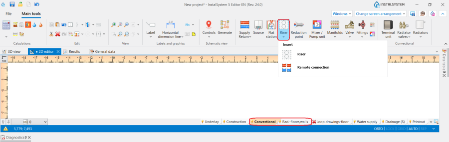
1. Insert Riser for Convectional and Radiant systems. - section Water supply for Water supply systems
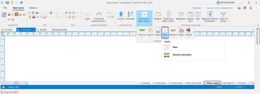
2. Insert Riser for Water supply systems. - section Drainage (S) for Sanitary drainage systems
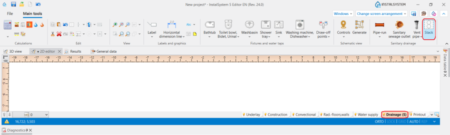
3. Insert Stack for Sanitary drainage systems.


EXAMPLE OF USE
Inserting a riser that runs through several storeys
- Insert Riser into one of the plan drawings.
- Enter the symbol in the Data table and select the starting and terminal storeys.
- Make connections to the riser on all storeys using Pipe-run.
Creating Drainage stacks with deviation
In multi-storey buildings, it can often happen that Drainage stacks should have a deviation (different XY coordinates) across different storeys, but should be considered as one, covering the entire height of the building. For such cases the following steps should be carried out:
- Put two or more Drainage stacks on floor plans, specify the Position and storeys range for each;
- All subsequent Drainage stacks should have one common storey in their ranges. A connection will automatically be created on this common storey;
- For the highest Stack in series, the type of Element on top of stack should be specified, e.g. Vent pipe;
- For the remaining, set Element on top of stack as Connection to the stack above and then select in the data field Connect to the stack having symbol the symbol of Stack, to which the connection is to be created.
Optionally the following values can be adjusted:
the Offset angle (Angle of offset from vertical direction) at which the connector is to be led out (offset);
for the lower part, Distance from ceiling of the conn. to stack above of the point, from which the connection will be lead out. - After checking the connections, assess the effect in the 3D view and adjust the above data if necessary.
When carrying out the above steps, it may be more convenient that the symbols of subsequent parts are different, but once the whole element has been correctly generated, all parts of the Stack with deviation can be assigned with the same symbol.
This procedure applies only to Drainage stacks without parallel ventilation.
ADDITIONAL INFORMATION
In cases where it is necessary to make connection of the pipe section to the Riser at the different elevation, modify the connection elevation. Does not apply to the scope Sanitary drainage systems.
| If you have any comments on this article, please send us a short message at info@instalsoft.com. |
|---|