Designing of water supply system installation
| Product | InstalSystem 5 |
| Type of article | DESIGNING LESSON |
| Source for translation | 2026-03-04 |
Scope of lesson
The article presents how to design internal sanitary systems (hot, cold water, hot water circulation piping). The example is based on a project prepared for a three-storey unifamilar house with a basement.
Modules and program configuration
- InstalSystem 5 with the module:
- Tap water systems,
- Tap water extensions - for output time calculations and for using water treatment devices.
The videos present the topics described in this article, but they aren’t a recording of this lesson.
Project file
The project file used in this lesson: Water supply system in residential building (example for the lesson).
Initial state
The project contains complete default data configured in the template file. The building structure has been elaborated on the basis of DWG layouts.
For more information, see: Preparation of building structure.
Steps to perform
Opening the project file
- Open a new project.
For more information, see: Project and application management - Choose the required template file (optional).
For more information, see: Template files - (alternatively): Open an existent file with a building structure. If it has been prepared with a different package configuration, import general data and settings from the template.
For more information, see: Template files.
Defining catalogues and general data
Correction of general data is not necessary if we begin work with a template file dedicated to such a scope. Correction is necessary if we begin work with a file that has been elaborated with a configuration without tap water systems module.
- Project scope - define project scope: Water supply systems.
- Catalogues – choose catalogues according to the list in the project table in scope of:
- pipes and fittings,
- Flat stations,
- insulation,
- tap assemblies and water outlet points,
- valves and fixtures.
- Water supply systems:
- Calculation standards and options:
- specify the number of hydrants for the listed locations,
- Calculation standard - choose the correct norm indicating method of flow calculation,

1. Calculation standard. - optionally, enable the point Calculations of hot water discharge time and select the Comfort level,
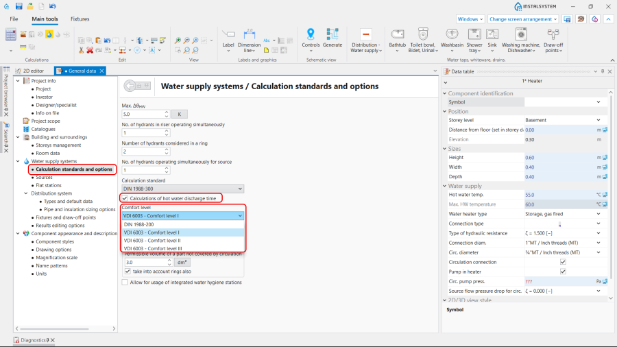
2. Comfort level.
- Sources
- Default building type
- Default cold water temp.
- Default hot water temp.
- Flat stations:
- Type and parameters by default
- Distribution system
- Types and default data
- Default pipe types: Cold water pipe-runs
- Default pipe types: Hot water and circulation pipe-runs
- Default valve types
- Default types of fittings and manifolds
- Pipe and insulation sizing options
- Types and default data
- Fixtures and draw-off points
- Default fixtures and their default water outlet points
- Frames (optional)
- Default connection systems
- System of connections for other water outlet points - according to the applied pipe system
- Calculation standards and options:


Editing sanitary installation
Perform inserting and graphical edition with AUTO mode on (for chosen layers).
Water taps, whiteware, drains.
- Select the Water supply editing scope.
- Insert fixtures and water taps in proper rooms.
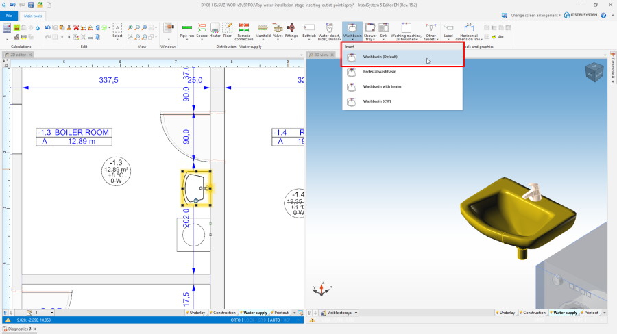
3. Water taps, whiteware, drains.

Riser
- Insert Riser and configure it in scope of:
- Symbol
- Connections
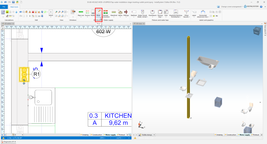
4. Riser.

Source
- Insert Source and configure it in scope of:
- Connections
- Graphical presentation
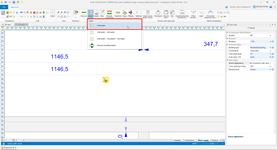
5. Source.

Optional: Water treatment device
- Insert Water treatment device and select its Type from the list offered in the Data table window:
- Water purification device
- Potable water treatment device
- Water softening device

6. Water treatment device.

Note:
- These elements change the state of water according to their purpose, which is reflected in the parameter Purpose of the medium, visible in the pipe-run hint after the treatment device;
- The program does not control the mutual order of Water treatment device elements of indicated types. There is no requirement to use all of offered from the list. This depends on the needs of a particular project;
- The hydraulic resistance of Water treatment device is significant, so the use of the elements most often requires high supply pressure or the use of the Pressure boosting device.
Optional: Pressure boosting device
- Insert Pressure boosting device.
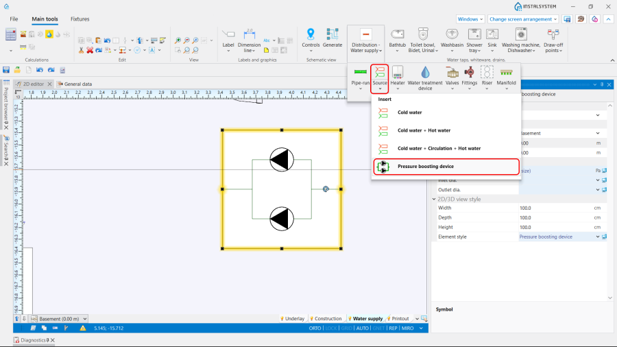
7. Pressure boosting device.

Heater / Flat station
- Insert Heater / Flat station and adjust the data in the Data table window.
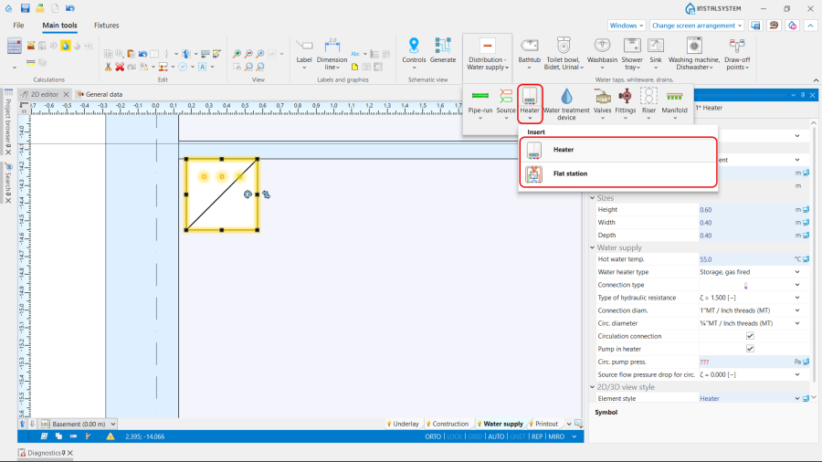
8. Heater / Flat station.

The detailed path of using Flat station elements in designed installations can be found here: Designing installations with flat stations.
Remote connection
Use Remote connection where necessary to connect elements of the installation, and specify the type of Connections in the Data table window.

Distribution network
Connect the inserted elements by various pipe feeds with correct spacing between them, using the AUTO and ORTO working modes.
Circulating piping should be connected hot water pipe feeds at the water outlet points by drawing circulating pipe feeds from the riser peak.

Connect water outlet points with the water distribution installation with the Automatically connect terminal units function.
Installation structure correctness verification
- Verify correctness of the installation structure with the Check connections function (shortcut: Shift + F2).
- Verify correctness of the installation structure and detect collisions with3D view.
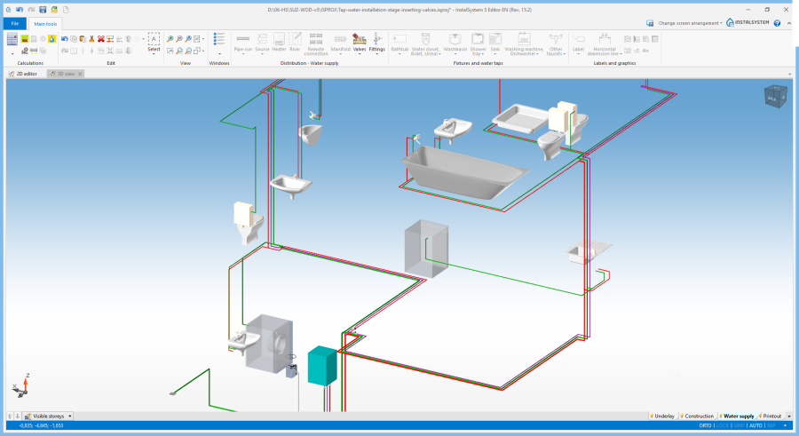
11. Installation structure correctness verification.

Further editing of the installation
Inserting Valves and Fittings
- Insert Non-return, shut-off and ball valves, Backflow preventers, Circulation controller, Pressure reductor/controller.
Valves may be moved in 3D view vertically on vertical sections if needed. In addition, while changing Rotation angle in Tabeli danych, it is possible to rotate valves about the pipe feed axis.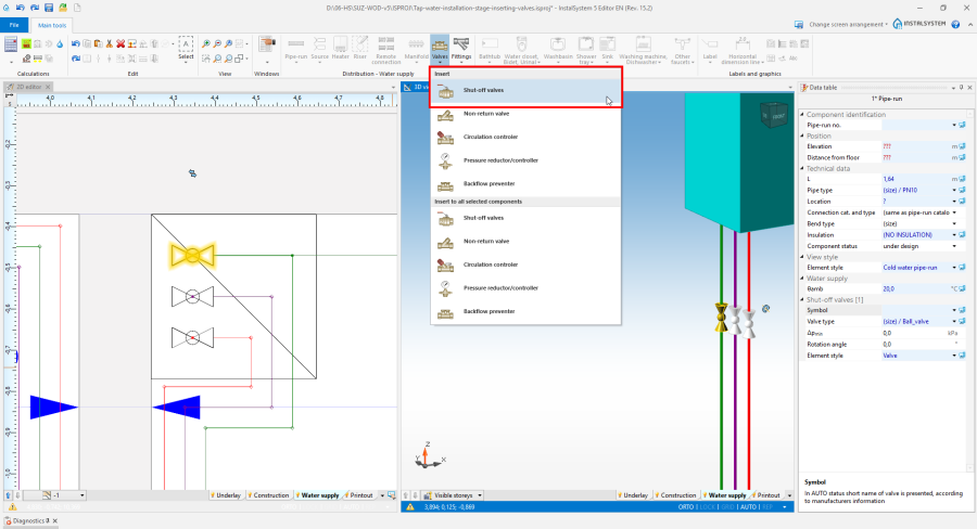
12. Valves. - Insert Non-return, shut-off and ball valves, Filters, Water meter, etc.
Fittings may be moved in 3D view vertically on vertical sections, if needed. In addition, while changing Rotation angle in Tabeli danych, it is possible to rotate valves about the pipe feed axis.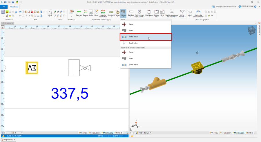
13. Fittings. - (Optional) Use of modules with fittings. For more information, see: Creating and using modules with fittings in heating and water supply installations.


Inserting Safety valve and Expansion vessel
- Insert Safety valve and Expansion vessel. Connect the elements with the installation via the No medium flow pipe feed type.

14. Safety valve and Expansion vessel.

Editing data of installation elements
Water taps, whiteware, drains.
- Correct Distance from floor, if necessary;
- Correct Demand type, if necessary. For more information, see: Demand type of water taps;
- Correct / complete System of connections for other water outlet points.
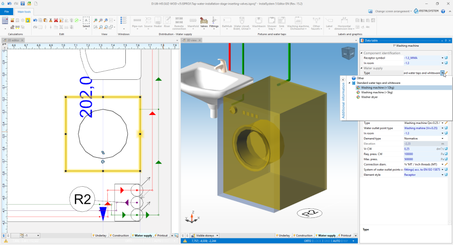
15. System of connections for other water outlet points. - Indicate the particular receiver for Hot water Discharge time analysis (in an area supplied from a single hot water Source and a single Circulation point, only one receiver can be indicated).

Pipe-run
- Correct Connection cat. and type and Bend type, if necessary.
Source
- Correct Source elevation, if necessary
- Enter Avail. press. if pressure in the external water supply system is known.
Heater
- Correct Distance from floor if necessary,
- Complete Type of hydraulic resistance,
- Complete Source flow pressure drop for circ..
Calculations and diagnostics
- Run the Water supply systems calculations by clicking on the
 icon located in the Calculations section on the toolbar.
 - The calculation results can be verified in the Results tables and directly on the drawings:
- Selected supply pressure and obtained available pressure at receptors,
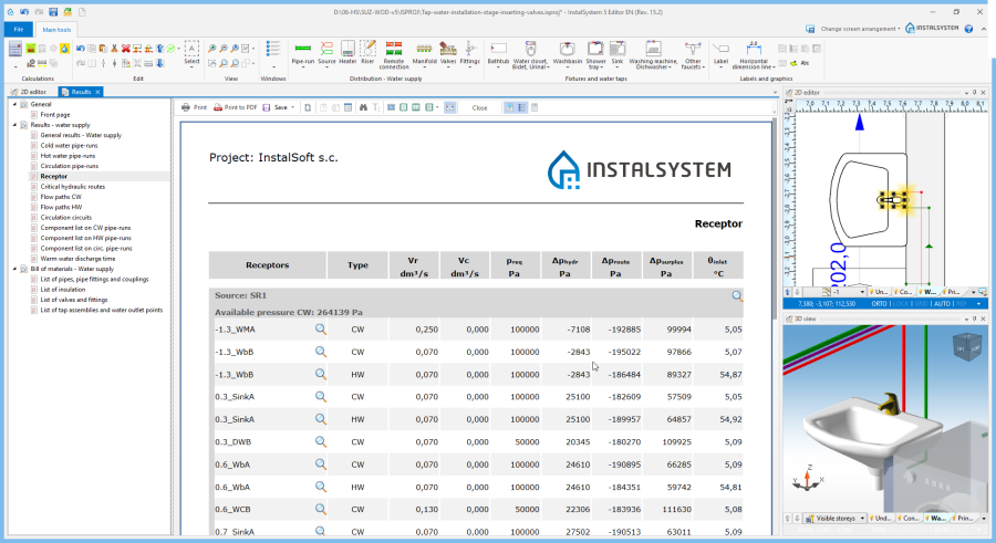
16. Receptor. - Calculations of circulation circuits and their balancing,
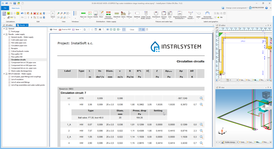
17. Circulation circuits. - Pipe-run diameters and insulation,

18. Pipe-run diameters and insulation. - Selection of nodes and connections,

19. Selection of nodes and connections. - Selection of valves and fittings,
- Calculation of pressure booster circuit and pressure regulator parameters,
- Obtained Hot water discharge time.
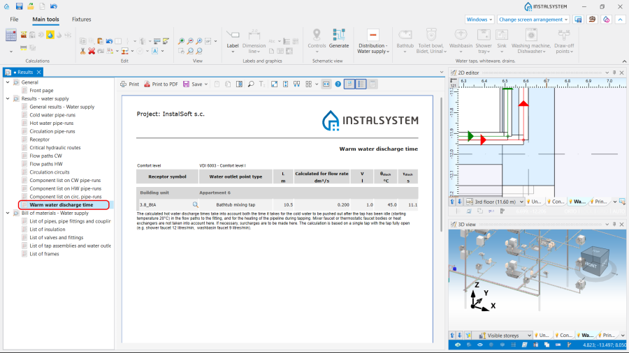
20. Hot water discharge time.
Note: Every item of the installation presented in the the Results tables can be found in active windows by using icon.
icon.
- Selected supply pressure and obtained available pressure at receptors,


For more information, see: Calculations and diagnostics.
Generating schematic views
The schematic view will be generated automatically. For more information, see: Automatically generate schematic views.

Preparing drawings for printing/exporting
Insertion and verification of labels for the following installation elements:
- Source,
- Pipe-run,
- Riser,
- Valves,'Fittings and 'Pump,
- Pressure boosting device and Pressure reductor/controller,
- Heater and Flat station.
Edit the configuration, if necessary. For more information, see: Label editing.
For more information, see: Preparation of drawings for export/printing.
BIM - Export of the installation to an IFC model
Specify the required settings and execute export of the installation using the IFC file export icon on the Main tools bar in the Printout and export section when the Printout editing scope is active.

For more information, see: BIM - Export of installation and construction data from the project to IFC models.
| If you have any comments on this article, please send us a short message at info@instalsoft.com |
|---|