Preparation of building structure - Roof modeling: Difference between revisions
Klintsevicho (talk | contribs) |
Klintsevicho (talk | contribs) No edit summary |
||
| Line 69: | Line 69: | ||
===Working with IFC files=== | ===Working with IFC files=== | ||
The program automatically interprets ''<IS_TS id=Roof/>'' elements created in IFC format files.<br/>[[File: Creation of roofs Interpret IFC.png|900 px|left|thumb|8. <IS_TS id=rpCreateRoofsFromIfc/>.]]<br clear="all"/> {{Info}} [[BIM_-_Interpretation_of_IFC_elements_into_building_structure_elements_of_InstalSystem_5_package#Interpretation_of_roofs|Interpretation of roofs]].<br/><br/> | The program automatically interprets ''<IS_TS id=Roof/>'' elements created in IFC format files.<br/>[[File: Creation of roofs Interpret IFC.png|900 px|left|thumb|8. <IS_TS id=rpCreateRoofsFromIfc/>.]]<br clear="all"/> {{Info}} [[BIM_-_Interpretation_of_IFC_elements_into_building_structure_elements_of_InstalSystem_5_package#Interpretation_of_roofs|Interpretation of roofs]].<br/><br/> | ||
===<IS_TS id=ZmienStropWDach/>=== | ===<IS_TS id=ZmienStropWDach/>=== | ||
''<IS_TS id=rpGenerowanieKonstrukcji/>'' allows to create only one roof in a building. The rooms not belonging to the last ''<IS_TS id=iNameKondygnacja/>'' are covered from above with ''<IS_TS id=rpSSufitowGCh/>'' slabs. If the building construction foresees the presence of a ''<IS_TS id=Roof/>'' element in such a place, the ''<IS_TS id=Slab/>'' can be easily converted into a ''<IS_TS id=Roof/>'' using the ''<IS_TS id=ZmienStropWDach/>'' function by previously dividing the ''<IS_TS id=Slab/>'' with the ''<IS_TS id=rpPodzialElementowKonstrukcji/>'' operations. <br/>{{#ev:youtube|wp07qBUhLmY|900||||rel=0}} <br clear="all"/> | ''<IS_TS id=rpGenerowanieKonstrukcji/>'' allows to create only one roof in a building. The rooms not belonging to the last ''<IS_TS id=iNameKondygnacja/>'' are covered from above with ''<IS_TS id=rpSSufitowGCh/>'' slabs. If the building construction foresees the presence of a ''<IS_TS id=Roof/>'' element in such a place, the ''<IS_TS id=Slab/>'' can be easily converted into a ''<IS_TS id=Roof/>'' using the ''<IS_TS id=ZmienStropWDach/>'' function by previously dividing the ''<IS_TS id=Slab/>'' with the ''<IS_TS id=rpPodzialElementowKonstrukcji/>'' operations. <br/>{{#ev:youtube|wp07qBUhLmY|900||||rel=0}} <br clear="all"/> | ||
Revision as of 15:53, 25 November 2024
| Product | InstalSystem 5 |
| Type of article | FUNCTION AND TOOL |
| Source for translation | 2024-11-17 |
Description
The article describes the possibilities of preparing various kinds of constructions.
Functions and tools related to the creation or modification of the structure and related elements are the following:
- scope, tab:
- ,
- ,
- , For more information, see: Creation of dormers.
- ,
- ;
- scope, tab:
- ;
- scope, tab:
- ,
- (to create );
- Operations related to the creation of during preparation of :
- - ,
- (right mouse button context menu).
Attention! In order to view the effects of any changes made during editing it is necessary to invoke .
For more information, see: Preparation of building structure.
Location in the program
scope
Icons of tools and functions related to the creation of are accessible in the and partly in the window on the bar, section when editing is enabled.


scope
Icons of tools and functions related to the creation of and its elements from the IFC file are accessible in and windows on the bar, section when editing is enabled, tab.

Related operations
- operation is available in and windows on the bar, section when editing is enabled, tab. Allows to automatically generate on the basis of previously created and .
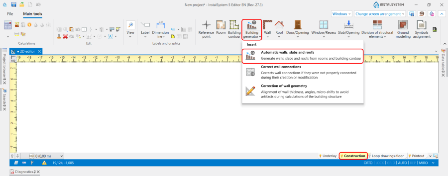
4. . - operation is available in and windows in the right mouse button context menu. Allows to convert element into .

5. .


Computation of building structure
- is available on bar, section .

6. .

Example of use
The detailed description of the creation of the basic design cases of roofs could be found here: Basic design cases.
The steps to be performed to create will depend on the format of the file used like an :
Working with DWG / DXF / PDF files
There are two ways to create in case the files of dwg, dxf of pdf formats are used:
- Manual creation. Use the tools available in the program and listed above.
- Automatic creation based on the function. In this case the program will generate the flat in accordance with the data set in the window, tab for the last . The roof edges with the corresponding elevations can be added manually.
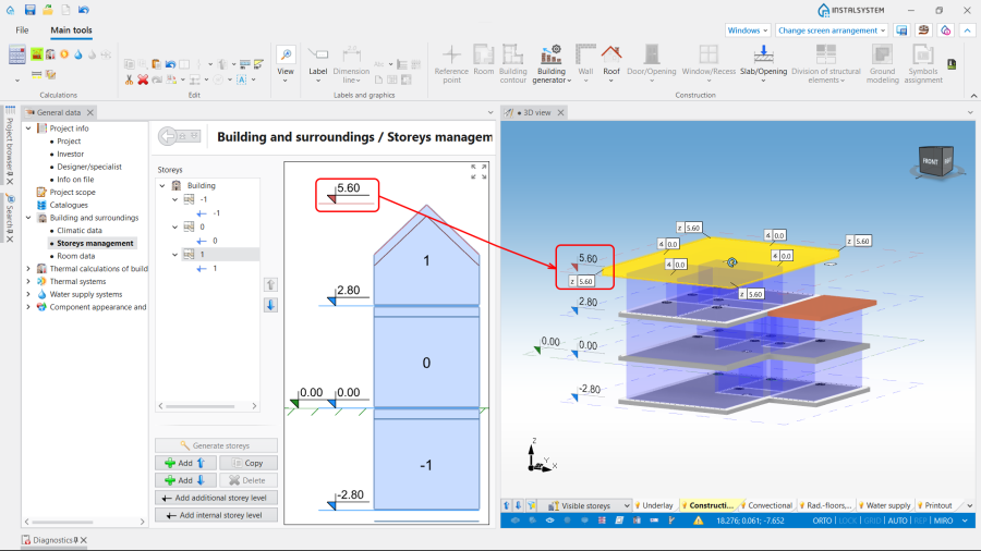
7. .

Attention! For user convenience, the program provides the opportunity to use two underlays - the plan view of the last storey and the roof plan view - on the same worksheet.
In order to be able to create correct using both underlayers, the following steps should be carried out:
- Make with roof plan view on the worksheet with imported plan view . For more information, see: Import underlay files;
- Scale the using the and the functions;
- to make the exact positioning of the underlays in relation to each other.
Working with IFC files
The program automatically interprets elements created in IFC format files.

For more information, see: Interpretation of roofs.
allows to create only one roof in a building. The rooms not belonging to the last are covered from above with slabs. If the building construction foresees the presence of a element in such a place, the can be easily converted into a using the function by previously dividing the with the operations.
The is the only element in the program that can create not only a strictly horizontal (or vertical) structural . Its further modelling is performed using the function, which . After the is performed, the modelled automatically cuts vertical partitions in the project.
The icon is located on the section, tab.
The following guidelines should be followed when positioning this element:
- The is placed on an already finished and calculated without any ,
- After inserting the , there is no need to cut holes for the windows. The program will automatically update the partition model after the have been carried out;
- Avoid inserting at the edges of the . If this design situation does exist, divide the into 2 elements and move them appropriately close to each other.
in the aspect of designed
The module(s) does not require a complete . However, the presence of a element means that the of designed is based on the model and the edge and correctly adapted to the available slopes. The absence of the element in the project causes the of the to be equal to the value of the taken from the .
Creation of a loggia
For more information, see: Creation of a loggia.
Additional information
The general theory of roof modelling is briefly summarized here: Roof modeling rules in InstalSystem-5.