Export / print results and drawings: Difference between revisions
Klintsevicho (talk | contribs) |
Klintsevicho (talk | contribs) |
||
| Line 29: | Line 29: | ||
==Location in the program== | ==Location in the program== | ||
* The icons with functions related to ''<IS_TS id=rpEksport2DToolbar/>'' and ''<IS_TS id=rpEksport3DToolbar/>'' are located on the ''<IS_TS id=NarzedziaGlowne/>'' bar when the ''<IS_TS id=lystrPrintPreview/>'' editing scope is active. The functions enables exporting graphics from the project file.<br/>[[Export print results and drawings location.png|left|thumb | * The icons with functions related to ''<IS_TS id=rpEksport2DToolbar/>'' and ''<IS_TS id=rpEksport3DToolbar/>'' are located on the ''<IS_TS id=NarzedziaGlowne/>'' bar when the ''<IS_TS id=lystrPrintPreview/>'' editing scope is active. The functions enables exporting graphics from the project file.<br/>[[File:Export print results and drawings location.png|900 px|left|thumb|1. <IS_TS id=rpEksport2DToolbar/> and <IS_TS id=rpEksport3DToolbar/> functions location.]]<br clear="all"/> | ||
* Outputting to a printer and to other file formats is effected in the ''<IS_TS id=Printouts/>'' window. The ''<IS_TS id=sBtnPrint/>'' function, available on the ''<IS_TS id=NarzedziaGlowne/>'' bar when the ''<IS_TS id=lystrPrintPreview/>'' editing scope is enabled, switches the program to that window. Alternatively this can be done by calling this window from the ''<IS_TS id=Windows/>'' menu on the ''<IS_TS id=NarzedziaGlowne/>'' bar.<br/>[[File: | * Outputting to a printer and to other file formats is effected in the ''<IS_TS id=Printouts/>'' window. The ''<IS_TS id=sBtnPrint/>'' function, available on the ''<IS_TS id=NarzedziaGlowne/>'' bar when the ''<IS_TS id=lystrPrintPreview/>'' editing scope is enabled, switches the program to that window. Alternatively this can be done by calling this window from the ''<IS_TS id=Windows/>'' menu on the ''<IS_TS id=NarzedziaGlowne/>'' bar.<br/>[[File:Export print results and drawings Print location.png|900 px|left|thumb|2. <IS_TS id=sBtnPrint/> functions location.]]<br clear="all"/> | ||
* | Prints and exports can be made of: | ||
* ''<IS_TS id=PrintoutCompositions/>'' - | |||
** ''<IS_TS id=PredefinedPrintout/>'' or | |||
** defined by the ''<IS_TS id=UserPrintout/>'', | |||
* ''<IS_TS id=GraphicPrintouts/>''. | |||
'''''Note:''''' To create ''<IS_TS id=GraphicPrintouts/>'' ''<IS_TS id=PrintoutPages_ElementName/>'' need to be inserted on the drawing. Every such component in the project is a new definition of the scope of printout / export of graphics. <br/> This can be done the ''<IS_TS id=Printouts/>'' window by using ''<IS_TS id=stractAddSelItemCaption/>'' function or using ''<IS_TS id=InsertPageLayout/>'' icon, available on the ''<IS_TS id=NarzedziaGlowne/>'' bar when the ''<IS_TS id=lystrPrintPreview/>'' editing scope is enabled.<br/>[[File:Suf-export-printout-pages.png|left|thumb|700px|3. <IS_TS id=InsertPageLayout/>]]<br clear="all"/> | |||
==Example of use== | ==Example of use== | ||
Revision as of 15:18, 19 May 2026
| Product | InstalSystem 5 |
| Type of article | FUNCTION AND TOOL |
| Source for translation | 2026-05-18 |
Description
The functionality of the program provides the opportunity of making 2D Export and 3D Export of results and drawings and printing them.
The project can be exported in the following file formats:
- IFC4,
- DWG / DXF,
- DWG(3D) / DXF(3D),
- glTF, PDF(3D), WebGL,
- PDF, JPG, BMP, PNG and others;
The Results tables can be exported in the PDF, XLSX, DOCX and other file formats.
Furthermore, the Bill of materials can be exported in GAEB 81, UGS, ISB and CSV formats.
Note: Exporting to IFC4, DWG / DXF, glTF files is effected by means of a dedicated function, whereas exporting to other file formats is done using Print functions. This process involves printing to a file of the selected type.
Location in the program
- The icons with functions related to 2D Export and 3D Export are located on the Main tools bar when the Printout editing scope is active. The functions enables exporting graphics from the project file.
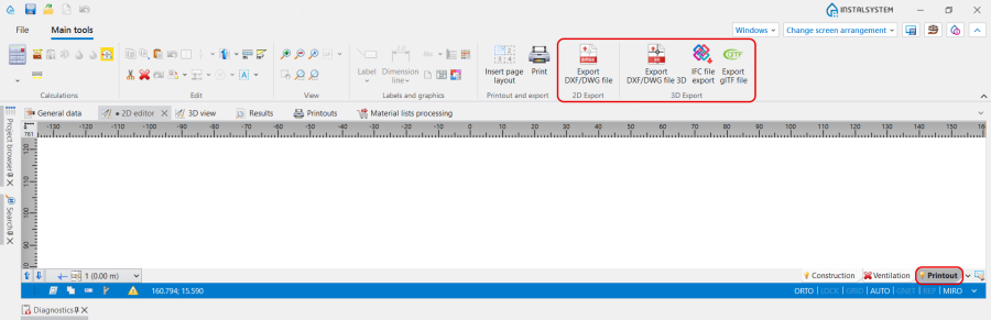
1. 2D Export and 3D Export functions location. - Outputting to a printer and to other file formats is effected in the Printouts window. The Print function, available on the Main tools bar when the Printout editing scope is enabled, switches the program to that window. Alternatively this can be done by calling this window from the Windows menu on the Main tools bar.
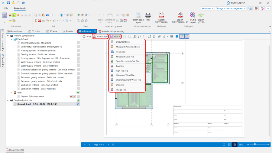
2. Print functions location.


Prints and exports can be made of:
- Printout compositions -
- Predefined or
- defined by the User,
- Graphical printouts.
Note: To create Graphical printouts Printout pages need to be inserted on the drawing. Every such component in the project is a new definition of the scope of printout / export of graphics.
This can be done the Printouts window by using Add function or using Insert page layout icon, available on the Main tools bar when the Printout editing scope is enabled.

Example of use
Exporting drawings to DWG format
For more information, see: Changing coordinates for exporting.
Printing / exporting drawings to an XLS file
Printing a drawing
Single page setup
The video shows how Drawing frame is set up
Multiple pages setup
The video shows how margins are set up in a multiple pages printout (Marking space)
Additional information
- When underlay drawing was imported with the Save underlay drawing -> In external file option and original location of the file is not available, the underlay layers cannot be exported. In such case, in order to have the underlay drawing included in the export or printout, it must be loaded again.
For more information, see: Import underlay files. - User-defined and saved printout compositions, in addition to pre-defined compositions, will also be available in other projects.
For more information, see: Printout compositions.
Preparing drawings for exporting/printing
Once all required changes have been made to the project and calculations have been completed, elements that complement the information provided in printouts can be entered into the project. These elements are of informative nature and do not affect the course of calculations. Inserting them into the project only at this stage is recommended, as iterative work with the project in earlier stages may also require modification of these elements. Therefore, inserting them in the final stage of work may be most effective.
Details of the types of elements available for specific types of installations can be found in the program application descriptions.
For more information, see: DESIGN APPLICATIONS.
- An example of this are Component labels available in the Main tools bar in the Labels and graphics section. A label is inserted by selecting the appropriate icon from the toolbar and clicking on the drawing component for which the label is intended. When a component with a label is selected in the drawing, the label style can be selected in the Data table window.

4. Component label
Label styles are customizable. It is possible to create and save many user-defined label styles.
For more information, see: Component appearance configuration.

| If you have any comments on this article, please send us a short message at info@instalsoft.com. |
|---|