Pump and Mixing unit: Difference between revisions
Klintsevicho (talk | contribs) No edit summary |
Klintsevicho (talk | contribs) No edit summary |
||
| Line 68: | Line 68: | ||
The ''<IS_TS id=iNameCOReduktorTemp/>'' characteristics are presented after performing ''<IS_TS id=sObliczenie/>'' of ''<IS_TS id=InstalacjeGrzewcze/>'': | The ''<IS_TS id=iNameCOReduktorTemp/>'' characteristics are presented after performing ''<IS_TS id=sObliczenie/>'' of ''<IS_TS id=InstalacjeGrzewcze/>'': | ||
* In the table, displayed in the working space, | * In the table, displayed in the working space, | ||
* On the element | * On the element ''<IS_TS id=Label/>'', | ||
* In the ''<IS_TS id=ResultModuleTitle/>'' tables,<br/>[[File:Pump and Mixer Results mixing unit.png|900 px|left|thumb|8. <IS_TS id=ResultModuleTitle/>.]]<br clear="all"/> | * In the ''<IS_TS id=ResultModuleTitle/>'' tables,<br/>[[File:Pump and Mixer Results mixing unit.png|900 px|left|thumb|8. <IS_TS id=ResultModuleTitle/>.]]<br clear="all"/> | ||
* In the ''<IS_TS id=iNameTabelkaMieszacza/>'' for the ''Mixing unit''. {{ | * In the ''<IS_TS id=iNameTabelkaMieszacza/>'' for the ''Mixing unit''. {{Info}} [[Designing_of_radiant_heating_floor_and_wall_installation#Mixer_.2F_control_unit_chart | <IS_TS id=iNameTabelkaMieszacza/>]]. | ||
Revision as of 13:25, 24 December 2025
| Product | InstalSystem 5 |
| Type of article | FUNCTION AND TOOL |
| Source for translation | 2025-12-17 |
Description
The article describes the ways of using such elements as Pump and Mixer / Pump unit in Designing heating systems with convective radiators and Designing of radiant heating floor and wall installation.
Location in program
Elements Pump and Mixer / Pump unit are available in the Distribution - thermal installations tab in the Main tools menu, when Convectional, Rad.-floors,walls or Rad.-ceilings editing scope is active.

Examples of use
Pump
The Pump is inserted as a separate element on the pipe-run section.
The following data can be adjust, if necessary, in the Data table window:
- H - Pump head;
- Rotation angle.
The Pump characteristics are presented after performing Calculations of Heating systems:
- In the table, displayed in the working space,
- On the element Label:
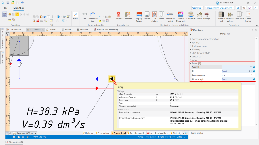
2. Pump.

Note: The appearance of the Label can be modified according to personal preferences. For more information, see: Label editing.
- In the Results tables:
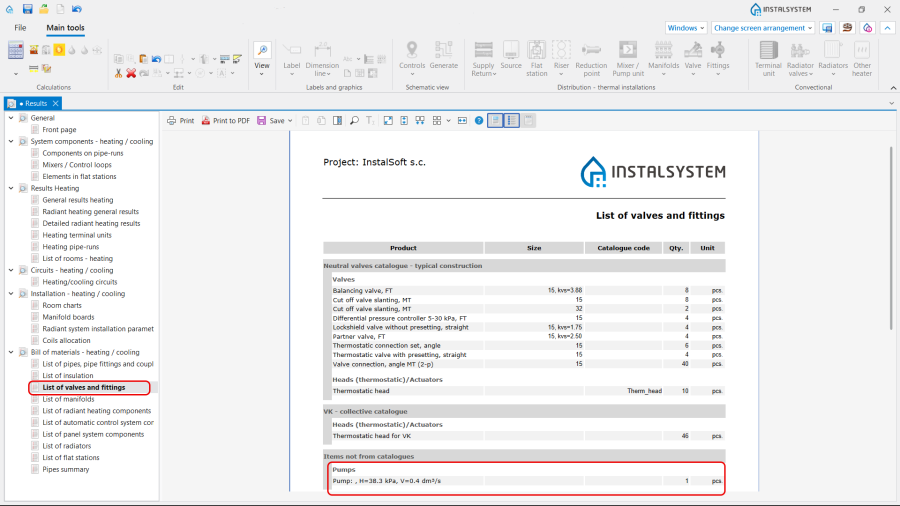
3. Pump in the Results tables.

Mixer / Pump unit
The Mixer / Pump unit is inserted as a group of elements, defined depending on the project purposes. The unit can be neutral or from the particular manufacture, selected from the Catalogues provided in the program. Note: To insert the Mixer / Pump unit element, use one of the following ways:
- Place the Mixer / Pump unit element on an already drawn pipe-run using the function Insert dividing point and deleting unnecessary pipe-runs.
- Draw sequentially the pipe-runs and the Mixer / Pump unit element.
Orientation
The Orientation of the Mixer / Pump unit is selected in the Data table window from the available variants.

Use
The Use of the Mixer / Pump unit is determined in accordance with the Project scope indicated in the General data window:
- Heating,
- Heating and cooling efficiency.
Type
The Type of the Mixer / Pump unit can be chosen from the:
- Neutral catalogue Standard mixers, pump and bypass units, provided by the program. Depending on the use of the Mixer / Pump unit , there are three variants be selected:
- Mixing supply and return units,
- Pump units,
- Units with supply to return bypass.
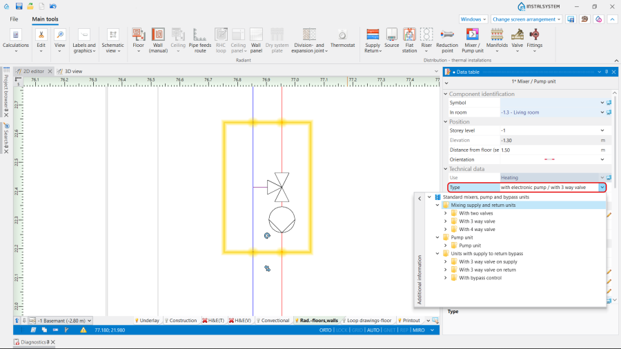
5. Mixer / Pump unit Type.
- Catalogues, provided by the particular manufacturer, selected in the General data window / Catalogues tab. For more information, see: Using catalogues and catalogues data in the project.

2D/3D view style
Presentation 2D and Presentation 3D of the Mixer / Pump unit can be:
- Detailed,
- Simplified.
The dimensions of the Mixer / Pump unit can be modified, if necessary.

Outlet temperature (mixing unit)
Outlet temperature (Heating) and Outlet temperature (Cooling) in the Mixing unit are determined automatically in accordance with the data set in the General data window for the Sources. If necessary, the values can be adjusted.

Results
The Mixer / Pump unit characteristics are presented after performing Calculations of Heating systems:
- In the table, displayed in the working space,
- On the element Label,
- In the Results tables,

8. Results. - In the Mixer / control unit chart for the Mixing unit. For more information, see: Mixer / control unit chart.
