Component appearance and descriptions configuration
| Product | InstalSystem 5 |
| Type of article | FUNCTION AND TOOL |
| Source for translation | 2022-12-01 |
Description
The functionalities contained in the Component appearance and descriptions configuration section enable the configuration of the appearance of components (e.g. in terms of colour or scale selection) and some editing parameters individually for each project. This allows the appearance of the drawings and the workflow to be better adapted to the individual requirements of the project in progress.
Location in the program
This feature is available in the General data window, Component appearance and descriptions configuration tab.

Example of use
Component styles tab
The tab provides a list of components that can be inserted in the graphical editor, allowing the selection of a component for appearance editing in 2D editor and in 3D view. For most components, two windows are displayed - one defines the styles of the component, the other the label styles of that component. However, style editing and label inserting is not available for all components.

Within the scope of existing styles it is possible to:
- modify:
- the type, colour and thickness of lines,
- the fill colour and transparency,
- 3D colour and 3D transparency;
- change the name;
- create new styles of components;
- copy;
- delete;
- reposition in the style list;
- Restore default program settings:
- globally for all components or for a selected component,
- separately the component appearance and the label appearance;
- save the configured styles as a template file For more information, see: Software configuration;
- load the default settings from a template:
- globally - labels and styles for all components,
- for a selected component: separately the component appearance and the label appearance.
Label editing
For labels, in addition to the basic style modification features, there is an Edit label window which enables:
- specifying the shape of the label;
- specifying the default label position;
- text formatting;
- displaying/concealing the line connecting the label with the component and configuring the style of that line.
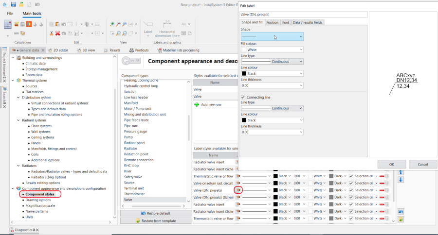
3. Edit label

Style selection criterion
A style may have an automatic style selection criterion enabled, which upon configuring will automatically assign a style to a component identified by the criterion. If a component has more than one style that can be assigned to it based on the criterions, then the style automatically assigned is the first that meets the criteria in the styles list.
Selecting a style in the data table
The appearance of a component and its label can be edited in the Data Table by specifying a style individually or collectively, by selecting it from among the styles predefined in Component styles:
- upon selecting the component in the plan view or 3D view in the 2D/3D view style and Label sections:

4. Data table-2D/3D view style - upon selecting the component in the schematic view in the View style (Schematic view) and Label(Schematic view) sections:
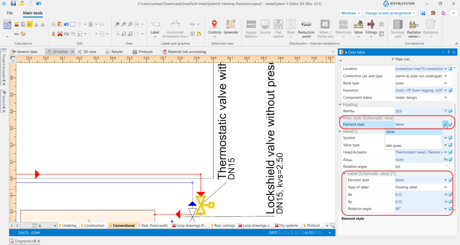
5. Data table-Label(Schematic view)


Drawing options tab
Depending on the selected project scope, the tab enables:
- selecting a drawing standard from the list of standards;
- checking/unchecking additional options pertaining to the design drawing appearance and printout.
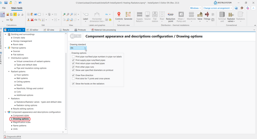
6. Drawing options

Magnification scale tab
This tab enables modifying the reference scale, changing the fittings drawing size and taking into account the diameter of the connections for each type of sheet separately.

Name patterns tab
This tab enables editing of the name patterns automatically assigned to selected components in the project.
The names are assigned automatically when the field in the Data table window of selected components includes the fields Symbol, Name or other identifying field, in the ![]() state.
Instructions for the name pattern defining is accessible upon clicking the
state.
Instructions for the name pattern defining is accessible upon clicking the ![]() icon in each row.
icon in each row.
The rows displayed depend on the settings made in the Project scope tab.

Units tab
This tab, depending on the selected project scope, enables selecting:
- the set of symbols of selected quantities in thermal calculations;
- the unit shown for selected quantities in water supply systems.
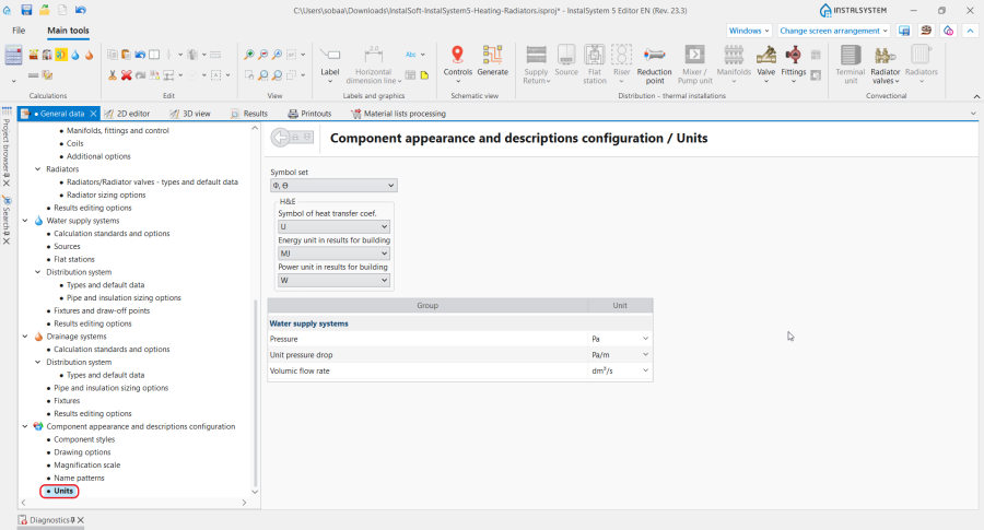
9. Units

Additional information
Components with additional appearance editing features
- Room - Floor dimming change,False ceiling dimming change);
- Opening in a wall - setting of the glass pane tinting colour and degree;
- Coil configuration - Different circuit colours,Pipefeeds use same colour as coil.
| If you have any comments on this article, please send us a short message at info@instalsoft.com. |
|---|