Designing of radiant heating floor and wall installation
| Product | InstalSystem 5 |
| Type of article | DESIGNING LESSON |
| Source for translation | 2025-01-11 |
Scope of lesson
This article presents the method of designing radiant heating systems (dry and wet):
The example shown is based on a design for a single-family two-storey house with no basement.
Modules and program configuration
The InstalSystem 5 includes the following module:
- Radiant systems.
The videos present the topics described in this article, but they aren’t a recording of this lesson.
Project file
The project file used in this lesson: Radiant heating floor and wall system in single family building (example for the lesson).
Inital state
The project includes a complete set of default data defined in a template.
The rooms arangement was based on base drawings in DWG format. More details in: Table of project example.
Steps to perform
Designing an installation - wet radiant systems
Editing general data and creating the building structure
Open new project file
- Launch InstalSystem 5.
- Open a new project and choose the preferred file version. For more information, see: Project and application management.
- Select the appropriate template. For more information, see: Template files.
Define catalogues and general data
For more information, see: Using catalogs and catalogs data in the project.
Declare General data in default data:
- Storeys management - add the required number of storeys. For more information, see: Preparation of building structure.
- Catalogues - choose catalogues according to the list in the Project table with regard to:
- Radiant systems
- Pipes and pipe fittings
- Insulation
- Valves and fittings
- Thermal systems - append information for:
- Distribution system
- Types and default data
- Radiant systems
- Floor systems
- Wall systems
- Manifolds, fittings and control
- Thermostats - options to choose from:
- in rooms data
- graphical (in the plan view).
- Thermostats - options to choose from:
- Distribution system
Prepare building structure
- Prepare the building structure as described in: Preparation of building structure - Rooms layout.
- The following data need to be modified:
- For the Room components of the Bathroom type, in the Data table window change the value in the Design temp. field to 24°C, for the Room components of the Lobby type change the value to 16°C.
- Define the maximum permissible temperature of floor surface by selecting the appropriate room type in the Heating section.
- For unheated rooms enter the heat loss coefficient equal to "0". For more information, see: Preparation of building structure.
- Verify the correctness of the structure created in 3D view. For more information, see: Viewing the created building structure.
- Select the appropriate option in theRoom thermostatbox in the room data table if Thermostatsis selected: in rooms data
Editing an installation - wet radiant system
Inserting Heating/Cooling Zone components
- Insert Heating/Cooling Zone components in selected rooms.
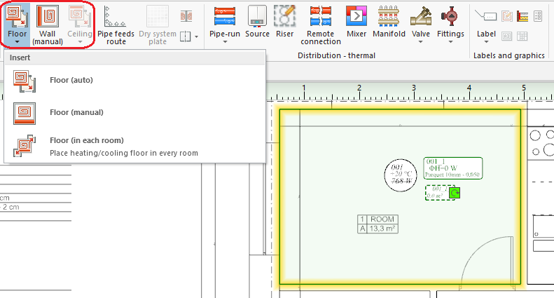
1. Inserting Heating/Cooling Zone - Cut out appropriate fragments of: Heating/Cooling Zone and/or change their shapes to adapt them to occupied areas (stairs, bathtubs) in rooms.
- Divide selected areas of Heating/Cooling Zone with regard to required expansion allowances. For more information, see: Heating/cooling zone.

Editing heating/cooling zone data
- Selecting a covering.
Mark selected Heating/Cooling Zone components and specify the type of Covering in Data table window.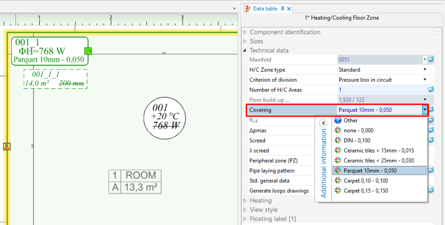
2. Covering - Change type for Heating/Cooling Zone.
- Mark these Heating/Cooling Zone where significant surface area is occupied by pipe feeds and change their type to Heated/cooled by pipe feeds. Remember in this case to remove connections with the manifold.
- Mark these Heating/Cooling Zone where no loops are to be arranged and change their type to Without pipes.
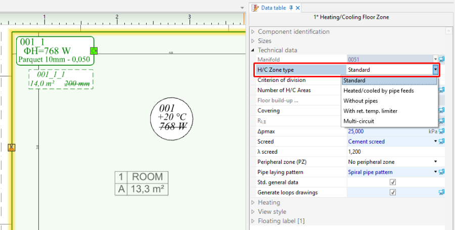
3. Typ Heating/Cooling Zone.
- Determining the presence of peripheral zones.
Specify and configure Peripheral zone (PZ).For more information, see: Defining a peripheral zone.


Inserting Thermostat components
- If Thermostats is selected: graphical (in the plan view), insert the Thermostat element in the selected rooms and adjust its type in the data table, if necessary.
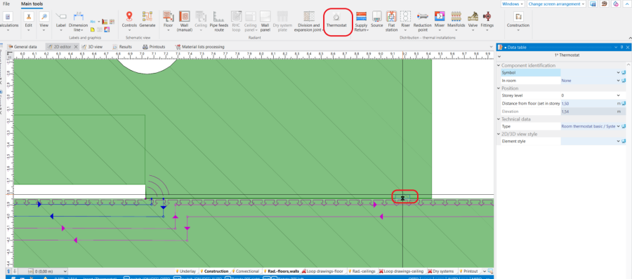
4. Inserting Thermostat component.

Inserting Manifold components
- Insert Manifold on every storey. Manifold is inserted in the drawing together with manifold cabinet.
For more information, see: Manifolds for radiant system and their accessories.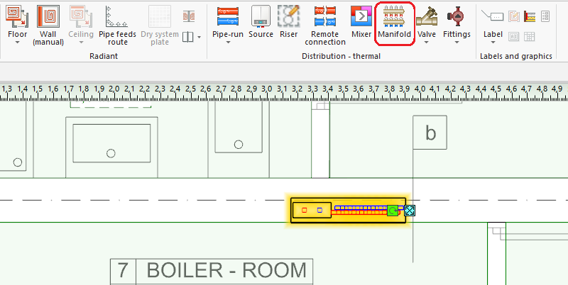
5. Inserting Manifold.

Pipe feeds routing
- Connect Heating/Cooling Zone with manifolds using Pipe feeds route. Pipe feeds route enables automatic generation of pipe feeds.
For more information, see: Editing pipe feeds in a radiant system.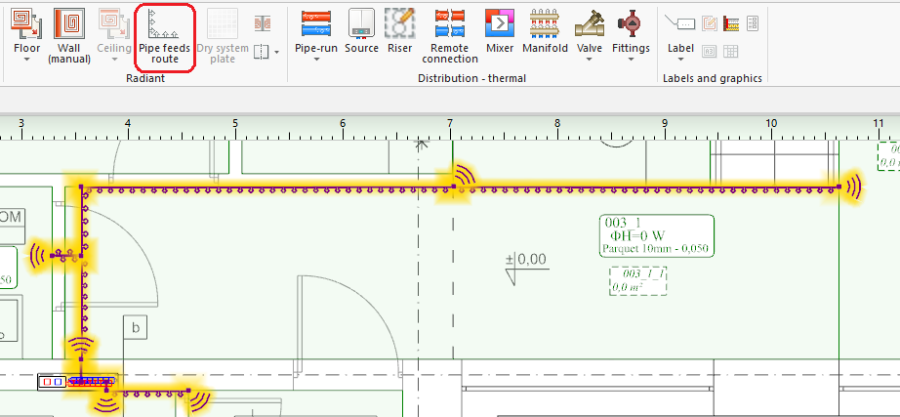
6. Inserting Pipe feeds route.

Editing an installation - feed to manifolds
Inserting Source
- Insert Source on the lowermost storey.
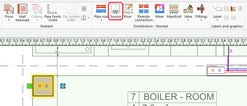
7. Inserting Source.

Inserting risers
- Insert Riser, assign a symbol to it and define its extent (from storey 0 to storey 1).
For more information, see: Connecting storeys with the "Stack" element.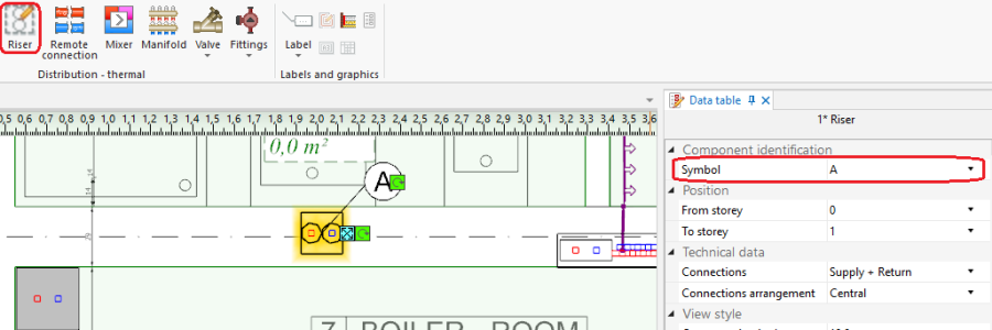
8. Inserting Riser.

Distribution
- Connect Source, Manifold, Riser with each other by drawing the network using the Pipe-run component and the AUTO and ORTO modes.
9. Connecting system components. - (Optionally) use the Automatically connect terminal units function.

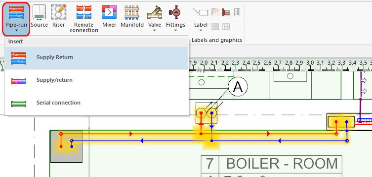
Inserting fittings
- Insert Valve onto pipe-runs.
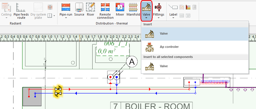
10. Inserting Fittings. - Select Valve type in Data table.
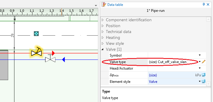
11. Valve type. - Use Copy - Paste to insert fittings of the same type onto other pipe-runs.


Verifying correctness of installation structure
- Verify the correctness of the installation structure using the Check connections function (Key shortcut: Shift + F2).
- Verify the correctness of the installation structure and find conflicts using 3D view.
For more information, see: Verification of the correctness of installation structure.
Adjusting installation parameters - manual modifications (optional)
- Impose manually the value (if determined by the heat source) or use Optimize supply temperature function. For more information, see: Optimization of the supply temperature of radiant systems.

12. Optimize supply temperature. - Change pipe spacing and temperature drop in individual loops.
For more information, see: Interactive calculations of radiant systems. - Change structure of heating floor\wall.
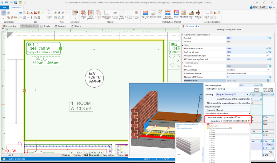
13. Floor build-up .... - Change Max. press. drop in circuit.
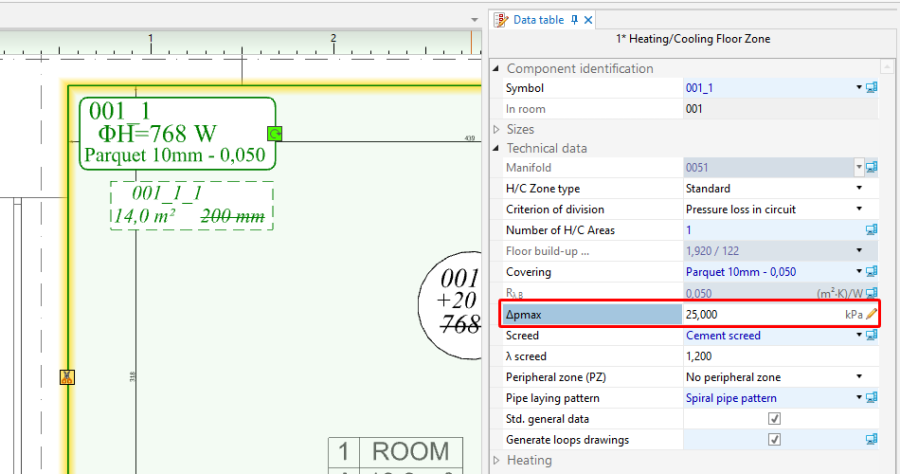
14. Max. press. drop in circuit.


Calculations and diagnostics
- Launch complete calculations by clicking the
 icon in the Calculations section of the toolbar.
 - Open the Diagnostics window by selecting it in the list of windows or by pressing F8.
- Carry out an interactive verification of results in the Interactive radiant systems calculations window.For more information, see: Interactive calculations of radiant systems.
- After calculations are completed verify the messages listed in the Diagnostics window. If error messages are displayed, these must be eliminated in the first place.
For more information, see: Calculations and diagnostics.
Particular attention must be paid to:- Coverage of heat or cold demand.
- Correct routes of feeds generated automatically.
- Layers of heating/cooling surfaces selected to take account of undesirable differences in the heights/thicknesses of adjacent surfaces.
Editing an installation and its parameters
At this stage manual modification can be made of the installation and its parameters within the following scope:
Modifying the dividing line of element Heating/Cooling Zone to elements Heating-cooling surface
For more information, see: Modifying the dividing line after automatic division.
Manual correction of automatically generated pipe feeds route
For more information, see: Pipe feeds route - manual correction of automatically generated pipe feeds route.
Appending drawings with radiant system loops
For more information, see: Appending drawings with radiant system loops.
Including drawing loop length in the calculations
For more information, see: How to include the drawing loop lenght in the calculations?.
Recalculation and verification of results
- Verify calculation results in the Results window:
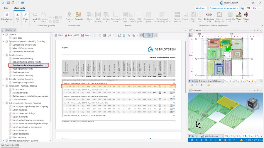
15. Results.
Note: Use icon to find any particular element in all active windows.
- Analyze the coverage of heat demand in rooms:

16. Coverage of required heating output. - Explore the bill of materials:
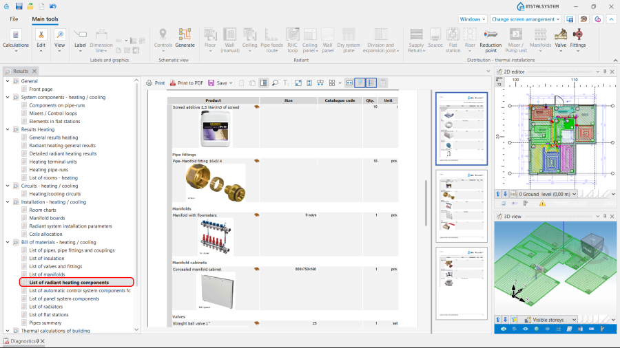
17. Bill of materials - heating / cooling - List of radiant heating components.
- Analyze the coverage of heat demand in rooms:
- Verify the system layout by means of the 3D view;
- Check the data of each element of the installation directly in the drawings.
For more information, see: Presentation of the calculations result.


Generating schematic views
The schematic view will be generated automatically. For more information, see: Automatically generate schematic views.

Prepare drawing for printing/export
Label
- Insert required labels onto components.
- Configure the label appearance (opc).
For more information, see: Label editing.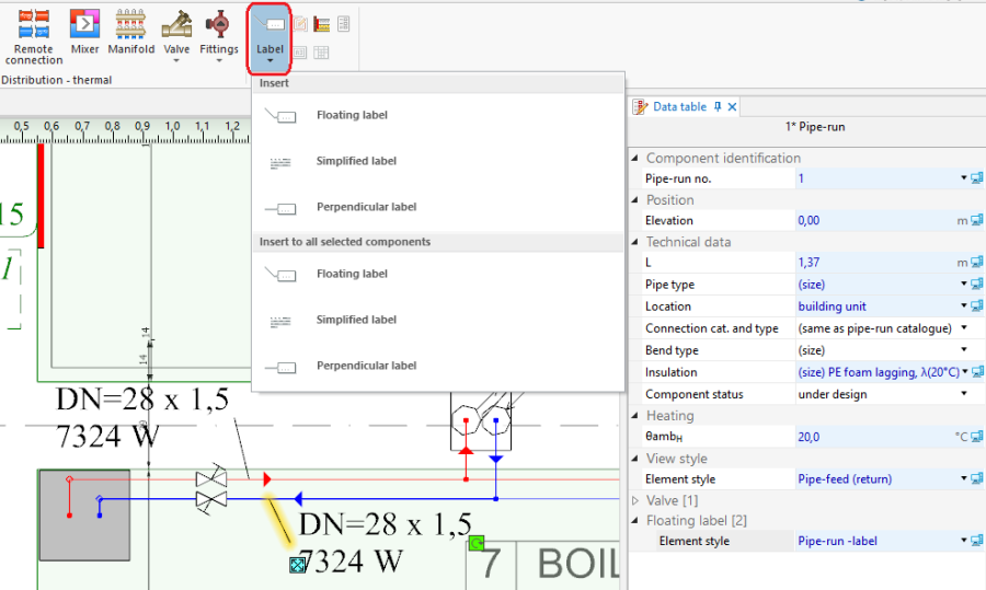
19. Inserting a Label.

Manifold table
- Insert Manifold table.
For more information, see: Manifold table.
Structure cross section drawing
- Insert Structure cross section drawing. Rescale and configure, if necessary.
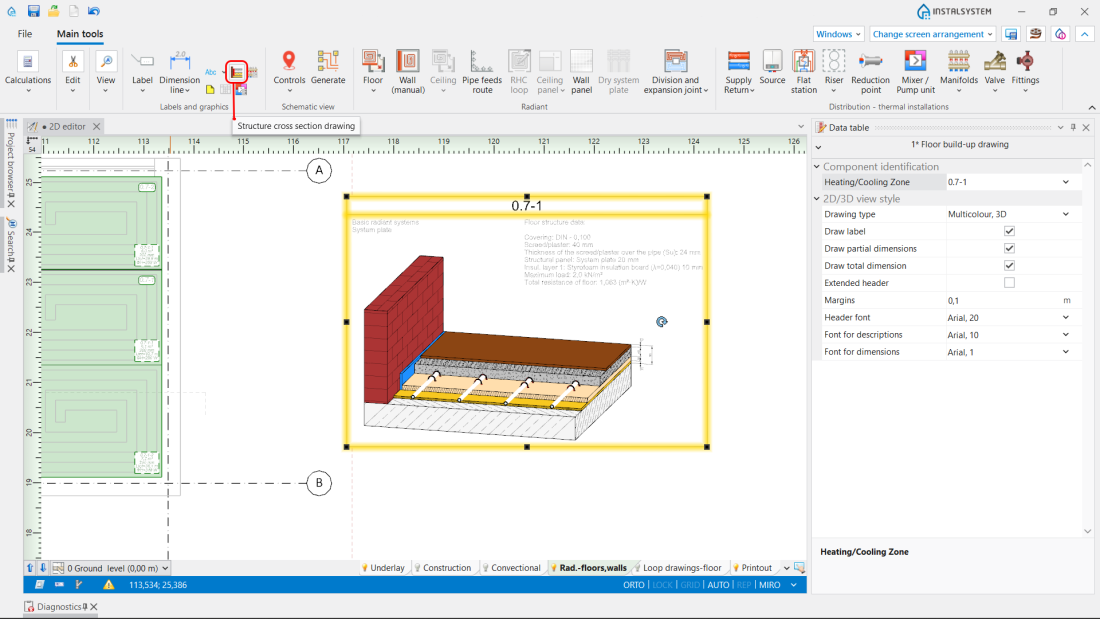
20. Structure cross section drawing.

Mixer / control unit chart
- Insert Mixer / control unit chart. Rescale and configure, if necessary.
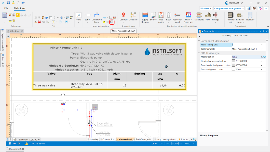
21. Mixer / control unit chart.

Drawing frame
- Insert Drawing frame.
- Select Drawing frame in Data table .
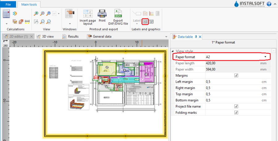
22. Inserting Drawing frame.

Drawing chart
- Insert Drawing chart.
- Enter the required data in Data table.
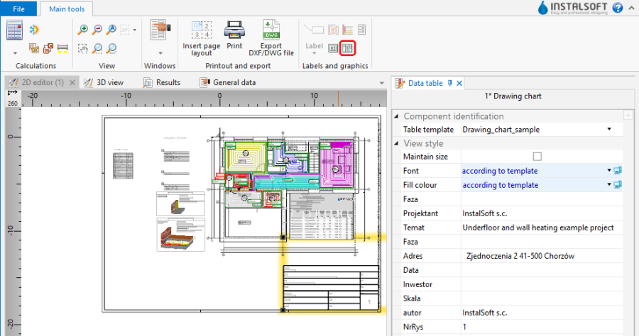
23. Drawing chart.

Print/export results
- Print/export drawings.
- Print/export tables.
For more information, see: Export / print results and drawings.
BIM - Export of the installation to an IFC model
Specify the required settings and execute export of the installation using the IFC file export icon on the Main tools bar in the Printout and export section when the Printout editing scope is active.

For more information, see: BIM - Export of installation and construction data from the project to IFC models.
Editing an installation - dry radiant systems
The course of designing dry systems essentially follows that of the wet systems.
Additionally it is possible within a Heating/Cooling Zone type component to insert dry system plates and cut them to fit within room borders or to fit to the edges of other plates. The resulting quantities of plates are then included in the bill of materials. In addition, when routing the feeds and loops, it is necessary to take into account the arrangement of grooves in the dry system plates.
Editing general data and creating the building structure
Specify default data in General data:
- On the Floor systems tab, field Default system / fastening method, select the dry system of the particular manufacturer.
- Other data in accordance with: Editing general data and creating the building structure.
Editing an installation - dry radiant systems
Inserting Heating/Cooling Zone components
- Insert Heating/Cooling Zone components in selected rooms. For more information, see: Heating/cooling zone.
25. Inserting Heating/Cooling Zone - Cut out appropriate fragments of: Heating/Cooling Zone and/or change their shapes to adapt them to occupied areas (stairs, bathtubs) in rooms.
For more information, see: Openings in heating-cooling areas zone.
Inserting dry system plates
- Add Dry system plate components to the project. For more information, see: Inserting plates in dry floor heating system.
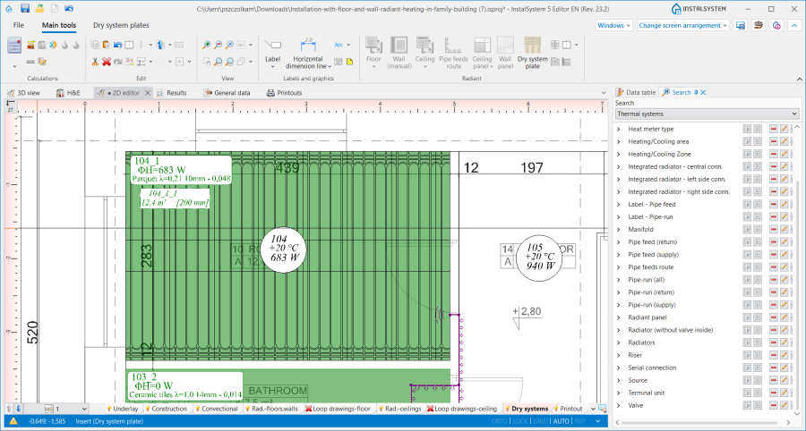
26. Inserting plates in dry floor heating systems.

Editing heating/cooling zone data
- Change of type for Heating/Cooling Zone.
- Mark these Heating/Cooling Zone where significant surface area is occupied by pipe feeds and change their type to Heated/cooled by pipe feeds. Remember in this case to remove connections with the manifold.
- Mark these Heating/Cooling Zone where no loops are to be arranged and change their type to Without pipes.
27. Type Heating/Cooling Zone.
Inserting Thermostat components.
Inserting Thermostat components.
Inserting Manifold components
- Insert Manifold on every storey. Manifold is inserted in the drawing together with manifold cabinet.
For more information, see: Manifolds for radiant system and their accessories.28. Inserting a Manifold.
Pipe feeds routing
- Connect Heating/Cooling Zone with manifolds using Pipe feeds route. Pipe feeds route enables automatic generation of pipe feeds.
For more information, see: Editing pipe feeds in a radiant system.29. Inserting a Pipe feeds route.
Edit installation - feed to manifolds
Edit installation - feed to manifolds.
Verify correctness of installation structure
Verify correctness of installation structure.
Adjusting installation parameters - manual modifications (optional)
Adjusting installation parameters - manual modifications.
Calculations and diagnostics
Editing an installation and its parameters
For more information, see: Editing an installation and its parameters.
Manual correction of automatically generated pipe feeds route
- After generating pipe feeds their arrangement in relation to the grooves in the Dry system plate components should be verified and adjusted manually, if necessary.
For more information, see: Pipe feeds route - manual correction of automatically generated pipe feeds route.
Appending drawings with radiant system loops
- After completing project calculations the arrangement of loops in relation to the grooves in the Dry system plate components should be verified. For more information, see: Manual editing of loop drawings in dry systems with guide plates.
Recalculation and verification of results
For more information, see: Recalculation and verification of results.
Generating schematic views
The schematic view will be generated automatically. For more information, see: Automatically generate schematic views.
Prepare drawing for printing/export
For more information, see: Prepare drawing for printing/export.
Print/export results
For more information, see: Print/export results.
BIM - Export of the installation to an IFC model
For more information, see: BIM - Export of the installation to an IFC model.
| If you have any comments on this article, please send us a short message at info@instalsoft.com |
|---|