Calculation of design heat load of rooms: Difference between revisions
Pszczolkam (talk | contribs) |
Pszczolkam (talk | contribs) |
||
| Line 45: | Line 45: | ||
#* ''<IS_TS id=rsEN12831_DaneMostkow/>'' | #* ''<IS_TS id=rsEN12831_DaneMostkow/>'' | ||
#* ''<IS_TS id=rsEN12831_SposobWyznaczaniaTempZDrugiejStronyDlaInnychGrupPom/>''.</br>[[File:Calculation_standards_and_options.png|900 px|left|thumb|1. <IS_TS id=rsDanog_Normy/>.]]<br clear="all"/> | #* ''<IS_TS id=rsEN12831_SposobWyznaczaniaTempZDrugiejStronyDlaInnychGrupPom/>''.</br>[[File:Calculation_standards_and_options.png|900 px|left|thumb|1. <IS_TS id=rsDanog_Normy/>.]]<br clear="all"/> | ||
====''<IS_TS id= | ===Edycja danych budynku i jego otoczenia=== | ||
[[File: | # Zakładka ''<IS_TS id=KTENazwaRodzaju/>'' - określić lokalizację budynku, poprzez wybór w liście pól: | ||
#* ''<IS_TS id=strOpisProjektuKraj/>'' | |||
#* ''<IS_TS id=strs_metkaidISFOZCDaneOgolneSZE_MiejscowoscMetka/>''.</br>[[File:Climatic_data.png|900 px|left|thumb|2. <IS_TS id=KTENazwaRodzaju/>]]<br clear="all"/> | |||
# Każda z miejscowości jest automatycznie przypisana do odpowiedniej stacji meteo, dla której w katalogu danych klimatycznych, zostały określone wymagane wartości, np.: | |||
#* ''<IS_TS id=sENDaneBudynkuTempZewnetrzna/>'' ''<IS_TS id=TemperaturaZewnetrznaOgrzewanieSymbol/>'' | |||
#* ''<IS_TS id=strl_expidISFOZCDaneOgolneSredniaTemperaturaZewnetrzna/>'' ''<IS_TS id=strs_expidISFOZCDaneOgolneSredniaTemperaturaZewnetrzna/>''. | |||
# Zakładka ''<IS_TS id=KTENazwaRodzaju/>'' - określić wartości w polu ''<IS_TS id=strTempOblPowDlaSzczelinDylatacji/>''. | |||
# Zakładka ''<IS_TS id=StoreyManagement/>'' - w razie potrzeby w oknie ''<IS_TS id=DataEditorTable/>'' dla elementu ''<IS_TS id=sBudynek/>'' skorygować jego ''<IS_TS id=pcstrXY/>''.</br>[[File:Storeys-management-ground-elevation.png|900 px|left|thumb|3. <IS_TS id=pcstrXY/> elementu <IS_TS id=sBudynek/>]]<br clear="all"/> | |||
# Zakładka ''<IS_TS id=Danog_BudynekSC/>'' - ustalić najważniejsze parametry budynku na potrzeby ''<IS_TS id=ObliczeniaCieplneBudynku/>'' w polach dostępnych na formatce. Widoczność niektórych danych na tej zakładce jest zależna od wyboru w polu ''<IS_TS id=strs_enumidISFOZCDaneOgolneNorma_StratyCiepla/>'' na zakładce ''<IS_TS id=rsDanog_Normy/>''. </br>Pola danych z czerwonymi znakami zapytania, jeżeli są ustawione w trybie ''<IS_TS id=automanAuto/>'' [[Plik:Auto-calculation-ikon.png|20 px|]], zostaną automatycznie uzupełnione po pierwszych obliczeniach. Na formatce dostępne są następujące dane, np.: | |||
#* Dane dotyczące konstrukcji budynku: | |||
#**''<IS_TS id=strs_enumidISFOZCDaneOgolneEN_TypKonstrukcjiBudynku/>'' | |||
#** ''<IS_TS id=strs_enumidISFOZCDaneOgolneSZE_SzczelnoscBudynku/>'' | |||
#** ''<IS_TS id=strs_enumidISFOZCDaneOgolneSZE_KlasaOslonieciaBudynku/>'' | |||
#** ''<IS_TS id=strl_expidISFOZCDaneOgolneEN_KrotnoscWymianPrzyRoznicy50Pa/>''. | |||
#* ''<IS_TS id=sParametryBudynku/>'': </br>[[File:Heat_loses_data_building_parameters.png|900 px|left|thumb|4. <IS_TS id=Danog_BudynekSC/>]]<br clear="all"/> | |||
#* ''<IS_TS id=OzcDomyslneUstawieniaWentylacji/>''. | |||
# Zakładka ''<IS_TS id=DanePomieszczen/>'' - określić najważniejsze dane pomieszczeń: </br>[[File:Room_data_pro.png|900 px|left|thumb|4. <IS_TS id=DanePomieszczen/>]]<br clear="all"/> | |||
#* ''<IS_TS id=strs_enumidISFPomieszczenieEN12831_TypUzytkowyPomieszczenia/>'' - w liście pola dostępne są domyślne elementy ''<IS_TS id=DefinicjaTypuPomieszczenia/>''. Dane i parametry obliczeniowe możliwe do zmodyfikowania lub zdefiniowana dla wybranych typów pomieszczeń widoczne są w oknie ''<IS_TS id=DataEditorTable/>'' po zaznaczeniu typu pomieszczenia w liście pola.</br> Dane wprowadzone dla pierwszego pomieszczenia w liście są domyślnymi danymi dla każdego wstawionego w projekcie elementu ''<IS_TS id=iNameKonstrPomieszczenie/>''. W razie potrzeby kolejność w liście należy zmienić przy pomocy strzałek. Dla każdego zaznaczonego elementu ''<IS_TS id=iNameKonstrPomieszczenie/>'' można zmienić ''<IS_TS id=strs_enumidISFPomieszczenieEN12831_TypUzytkowyPomieszczenia/>'' w oknie ''<IS_TS id=DataEditorTable/>'', dodatkowo istnieje również możliwość definiowania własnych typów pomieszczeń użytkownika. | |||
#* ''<IS_TS id=strs_enumidISFOZCDaneOgolneStrataCieplaCalcKindForNewPom/>'' - w przypadku pracy nad zakresem ''<IS_TS id=ObliczeniaCieplneBudynku/>'' należy wybrać opcję ''<IS_TS id=rsOZCPomieszczenieStrataCieplaCalcKindWgNormSC/>''. Wybór w polu jest propagowany do wszystkich elementów ''<IS_TS id=iNameKonstrPomieszczenie/>'' wstawionych w projekcie i może zostać ręcznie zmieniony w oknie ''<IS_TS id=DataEditorTable/>'' dla wybranych elementów. | |||
#* ''<IS_TS id=iNameJednostkaBudynkuPlural/>'' - w zależności od potrzeb projektowych ustawić w polu ''<IS_TS id=strCreateJBOnEachStoreyFalse/>'' lub ''<IS_TS id=strCreateJBOnEachStoreyTrue/>''. </br>{{Info}} [[Edycja danych Jednostek Budynku]]. | |||
</br> | |||
===Editing building structure data=== | ===Editing building structure data=== | ||
Revision as of 08:38, 22 August 2022
| Product | InstalSystem 5 |
| Type of article | DESIGNING LESSON |
| Source for translation | 2022-02-23 |
Scope of lesson
The article presents the procedure for preparing data for calculating the design heat load of rooms with the use of standard packages.
Modules and program configuration
- InstalSystem 5 package with the module:
- Heat loss (Heat loss)
Webinars
We encourage you to see the video from our webinars on the topics described in this article:
The webinars present the topics described in this article, but they aren’t a recording of this lesson.
Project file
The project file used in this lesson: Design heat load in residental building (example for the lesson).
Inital state
The project includes building structure (storeys, building units, rooms, graphical partitions) and starting package of standards.
For more information, see: Preparation of building structure.
Another project file contains definitions of partitions to be imported.
Steps to perform
Default data setting for the project
- Zakładka Project scope - włączyć zakres projektu: Thermal calculations of building.
- Zakładka Calculation standards and options - wybrać pakiet normowy i ustawić najważniejsze parametry do obliczeń cieplnych (widoczność niektórych danych na zakładce jest zdeterminowana przez wybór w polu Heat loss standard):
- Standards package
- Heat loss standard
- Heat loss to ground calculation method
- Calculation method for c.h. interruptions
- Thermal bridges calculation method
- Manner of making allowance for thermal bridges
- Determine temperature of adjacent space.

1. Calculation standards and options.

Edycja danych budynku i jego otoczenia
- Zakładka Climatic data - określić lokalizację budynku, poprzez wybór w liście pól:
- Country
- Town.

2. Climatic data
- Każda z miejscowości jest automatycznie przypisana do odpowiedniej stacji meteo, dla której w katalogu danych klimatycznych, zostały określone wymagane wartości, np.:
- External temperature, design θe
- Annual mean external temperature θm,e.
- Zakładka Climatic data - określić wartości w polu Air temperature in building separation gap.
- Zakładka Storeys management - w razie potrzeby w oknie Data table dla elementu Building skorygować jego Position.

3. Position elementu Building - Zakładka Heat losses data - ustalić najważniejsze parametry budynku na potrzeby Thermal calculations of building w polach dostępnych na formatce. Widoczność niektórych danych na tej zakładce jest zależna od wyboru w polu Heat loss standard na zakładce Calculation standards and options.
Pola danych z czerwonymi znakami zapytania, jeżeli są ustawione w trybie Auto 20 px|, zostaną automatycznie uzupełnione po pierwszych obliczeniach. Na formatce dostępne są następujące dane, np.:- Dane dotyczące konstrukcji budynku:
- Building structure type
- Building tightness
- Building sheltering class
- Air change rate at 50 Pa press. diff..
- Building parameters:

4. Heat losses data - Default ventilation settings.
- Dane dotyczące konstrukcji budynku:
- Zakładka Room data - określić najważniejsze dane pomieszczeń:

4. Room data
- Room type - w liście pola dostępne są domyślne elementy Room type definition. Dane i parametry obliczeniowe możliwe do zmodyfikowania lub zdefiniowana dla wybranych typów pomieszczeń widoczne są w oknie Data table po zaznaczeniu typu pomieszczenia w liście pola.
Dane wprowadzone dla pierwszego pomieszczenia w liście są domyślnymi danymi dla każdego wstawionego w projekcie elementu Room. W razie potrzeby kolejność w liście należy zmienić przy pomocy strzałek. Dla każdego zaznaczonego elementu Room można zmienić Room type w oknie Data table, dodatkowo istnieje również możliwość definiowania własnych typów pomieszczeń użytkownika. - Method of calculating Φ - w przypadku pracy nad zakresem Thermal calculations of building należy wybrać opcję Calculations acc. to standard. Wybór w polu jest propagowany do wszystkich elementów Room wstawionych w projekcie i może zostać ręcznie zmieniony w oknie Data table dla wybranych elementów.
- Building units - w zależności od potrzeb projektowych ustawić w polu Common to entire building lub Separate for storeys.
For more information, see: Edycja danych Jednostek Budynku.
- Room type - w liście pola dostępne są domyślne elementy Room type definition. Dane i parametry obliczeniowe możliwe do zmodyfikowania lub zdefiniowana dla wybranych typów pomieszczeń widoczne są w oknie Data table po zaznaczeniu typu pomieszczenia w liście pola.


Editing building structure data
Notion explanation:
- graphical partition - element of the building structure, such as walls, ceiling, roof, window, door etc.
- thermal partition - logical element being a fragment of a given graphical partition within a single soom. It is created automatically, and its purpose is to calculate and present heat loss based on partition transition in a single room.
- Cut out opening in slab for staircase between storeys 1 and 2.
Calculating building structure
For more information, see: Computation of building structure
Verification of the correctness of building structure
- Verify the correctness of storey and room locations within the Building structure editing scope.
For more information, see: Verification of the correctness of building structure - Verify graphically the correctness of creating thermal partitions within the H&E editing scope.
Thermal partitions are created, arranged and dimensioned based on physical partitions existing in the building structure. Identification of thermal partitions is effected during Computation of building structure . - Verify graphically the correctness of creating the component.
Data editing
Partition definitions
- Import Partition definitions from file.
- Create new Partition definitions.
Create new Partition definitions depending on requirements and define them as Part. with specified U or Part. with defined layers. - Assign Partition definitions to thermal partitions.
Assignment of Partition definitions may be effected:- automatically - upon selecting appropriate Default for this type option for the partition (name of partition in the list of partitions is highlighted), requires calling Computation of building structure ,

3. Default for this type
Automatic partition definition is defined according to the following criteria:- Any thickness - all graphic partitions of a given type, regardless of their thickness, shall have this definition (default option for partition definition: Partition with specified U),
- Match to thickness with tolerance - all graphic partitions of a given type, with Thickness of partition indicated, and with tolerance in Tolerance relative to thickness of graphical partition, ± shall have thi definition (default option for partition definition: Part. with defined layers and Non-uniform part.).
The aforementioned criteria regard walls, ceilings and windows; windows and doors are covered by the Default for this type general option.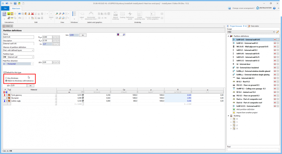
4. Any thickness
- manually.
- automatically - upon selecting appropriate Default for this type option for the partition (name of partition in the list of partitions is highlighted), requires calling Computation of building structure ,


Thermal linear bridge
- Verify/correct add-ons for the presence of components Thermal linear bridge depending on the calculation method selected in General data.
Building unit/Apartment
- Correct assignment of rooms to components Building unit/Apartment.
This may be done in the Data table window of room or using the "drag and drop" function in the building structure tree in the Project browser window.
Room
- Correct the Room types: bathrooms on both storteys, lounge, kitchen.
- Specify unheated rooms: entrance porch.
- Append Ventilation for heat loss data (V̇ex) for: bathroom and kitchen.
- Specify heated partitions - if the partition is to be integrated with planned surface heating or cooling, then select the Heated partition option for such partition.
- (optional) Add tables of cooling partitions if the actual building structure can be modelled graphically in the program.

5. Room data editing

Calculations and diagnostics
- Launch calculations by clicking the calculator icon Thermal calculations of building
 in the Calculations section of the toolbar.
 - Verify calculation results, paying attention to:
- error messages,
- room calculation results in the H&E window,

6. Calculation results for rooms - results of heat load Phi in room labels.
- (optional) distribute design heat load of rooms among other rooms.

Prepare drawing for printing/export
For more information, see: Presentation of the calculations result