Preparation of building structure: Difference between revisions
Pszczolkam (talk | contribs) |
Pszczolkam (talk | contribs) |
||
| Line 30: | Line 30: | ||
===Building structure=== | ===Building structure=== | ||
* Icons of components and functions related to the building structure are available in the ''2D Editor'' window on the ''<IS_TS id=NarzedziaGlowne/>'' bar in the ''<IS_TS id=lystrFloors/>'' section when the ''<IS_TS id=lystrFloors/>'' editing scope is enabled.<br | * Icons of components and functions related to the building structure are available in the ''2D Editor'' window on the ''<IS_TS id=NarzedziaGlowne/>'' bar in the ''<IS_TS id=lystrFloors/>'' section when the ''<IS_TS id=lystrFloors/>'' editing scope is enabled.</br>[[File:Toolbar_construction.png|900 px|left|thumb|3. Elementy konstrukcji budynku]]<br clear="all"/> | ||
===Computation of building structure=== | ===Computation of building structure=== | ||
Revision as of 11:31, 22 March 2022
| Product | InstalSystem 5 |
| Type of article | FUNCTION AND TOOL |
| Source for translation | 2022-02-24 |
Description
Artykuł opisuje różne możliwości przygotowania struktury budynku oraz sposób weryfikowania jej poprawności. Wybrany sposób tworzenia struktury budynku zależny jest przede wszystkim od tego jakie instalacje i w jakim zakresie będą projektowane oraz od tego jakie są dostępne dane źródłowe w zakresie konstrukcji i rzutów poszczególnych kondygnacji.
Jeżeli w projekcie nie są wymagane obliczenia strat ciepła zgodnie z normami, można zrezygnować z tworzenia pełnej struktury budynku z elementami konstrukcyjnymi, na rzecz struktury budynku z pomieszczeniami ręcznymi - wielokątami lub struktury budynku bez pomieszczeń.
We wszystkich wyżej wymienionych metodach każda kondygnacja stanowi osobny arkusz rzutu, na który można zaimportować podkład z pliku zewnętrznego.
Location in program
Storeys management
- Storeys management is available in the General data window w sekcji Building and surroundings.

1. Storeys management.

Import underlay
- Icons of components and functions related to importing underlays (base drawings) are available in the 2D Editor window on the Main tools bar in the Underlay section when the Underlay editing scope is enabled.

2. Importuj podkład

Building structure
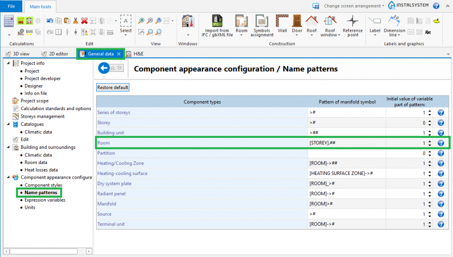
- Icons of components and functions related to the building structure are available in the 2D Editor window on the Main tools bar in the Construction section when the Construction editing scope is enabled.

3. Elementy konstrukcji budynku

Computation of building structure
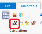
- Computation of building structure is available on the Main tools toolbar in the Calculations section.

4. Computation of building structure

Examples of use
Manual creation of building structure
Storeys
- Create the required storeys and append their data.
Underlay
Underlay (base drawing) is a two-dimensional (flat) graphical object retrieved from an external raster or vector file. The underlay itself does not provide building structure components, but it enables manual creation thereof adapted to the actual state of the building.
For more information, see: Import files
Room - manual creation of rooms
- Create a Room manually using a contour line
or by drawing a diagonal line. When a room is created by drawing a diagonal line disable the ORTO operating mode. After drawing the diagonal line complete the edition by right clicking.
Room - identification within area bordered with drawn partitions
Rooms can be created automatically in areas bounded by edges (surfaces) of the defined graphical partitions (walls, floor slabs, roofs). In this case it is necessary to draw graphical partitions in the project and to run Computation of building structure , which also enables adapting the partitions to the drawn plane of the roof. All operations that are to correct automatic rooms (deleting automatic rooms, changing their shape, room division and so on) must be completed with the correct result Computation of building structure .
- Place a series of Wall components by entering at the start the thickness of the wall in Data table and moving the cursor along the internal edges of the walls on the underlay. In underlays retrieved from a DWG file make use of the snapping to indicated layer feature. After placing Internal walls insert External walls in similar manner.
- Place the following components: Window, Door, Opening in wall, Recess.
- Place the following components: Slab. Outline of one storey is by default covered by a single slab.
- Insert: Roof.
- Create a multifaceted roof.
For more information, see: Preparation of building structure - Creation of roofs with different construction - Insert components Roof window
- Insert components: Opening in slab.
Opening in slab can be deleted by clicking
- Carry out Computation of building structure .
Computation of building structure launches a number of operations associated with providing a complete building structure:- cutting away partitions by the roof plane,
- automatic identification of rooms.
Numbering the rooms
- Symbols are assigned to rooms by selecting Symbols assignment and marking room labels in a desired sequence. That sequence defines the numbering order of the rooms.
- The program enables configuring the pattern of room numbering.
The numbering configuration shown below means that the room symbol consists of a storey symbol and of a two-digit number of the room on that storey. More information is displayed when the mouse cursor is positioned over .
.
5. Component name configutation window
For more information, see: Ground modeling

Manual editing of rooms and automatic identification of walls and slabs on an underlay
The operation of automatic identification of walls and slabs enables creating these partitions within spaces identified between rooms included in the project and the outline of the building.
To carry out the operation:
- In the project file with previously inserted rooms, make a building outline using the 'Building outline' function.
- Optionally: if the building outline is identical on a number of storeys, enter appropriate values in the fields 'from storey' and 'to storey' in the data table of the building outline component.
- Launch interpretation of external and internal walls and slabs based on rooms arangement and building outline using the Automatic walls, slabs and roofs function.
5.Automatic walls, slabs and roofs
For more information, see: Improvements of creating and managing Building units

Importing a complete building structure
Importing a building structure from a BIM (gbXML) compatible format
For more information, see: Import files
Importing a building structure from an InstalSystem 4 (ISB) project file
If necessary, manually correct or append the missing or incorrect components of the building structure thus obtained using the methods described above.
Verification of the correctness of building structure
Carry out the verification in the 3D view window
For more information, see: View navigation in the graphical editor