Pump and Mixing unit: Difference between revisions
Klintsevicho (talk | contribs) |
No edit summary |
||
| (One intermediate revision by one other user not shown) | |||
| Line 1: | Line 1: | ||
<!-- case 333279--> | |||
<IS_HELP id="HS208"/> | |||
{{Article table | {{Article table | ||
|commercial_product1=InstalSystem 5 | |commercial_product1=InstalSystem 5 | ||
| Line 78: | Line 81: | ||
[[Category:InstalSystem 5]] | [[Category:InstalSystem 5]] | ||
[[Category:FUNCTION AND TOOL]] | [[Category:FUNCTION AND TOOL]] | ||
<!-- Do not write text below this tag --> | |||
<br class="iwlinks"/>[[pl:Pompa i mieszacz|Pompa i mieszacz]] | |||
Latest revision as of 23:01, 17 March 2026
| Product | InstalSystem 5 |
| Type of article | FUNCTION AND TOOL |
| Source for translation | 2025-12-17 |
Description
The article describes the ways of using such elements as Pump and Mixer / Pump unit in Designing heating systems with convective radiators and Designing of radiant heating floor and wall installation.
Location in program
Elements Pump and Mixer / Pump unit are available in the Distribution - thermal installations tab in the Main tools menu, when Convectional, Rad.-floors,walls or Rad.-ceilings editing scope is active.

Examples of use
Pump
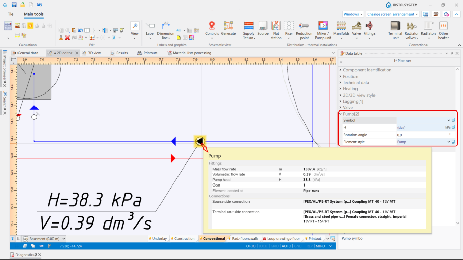
The Pump is inserted as a separate element on the pipe-run section.
The following data can be adjust, if necessary, in the Data table window:
- H - Pump head;
- Rotation angle.
If the Pump head is left to be sized by the program, the result can be read from the hint after performing Calculations of Heating systems:
- In the table, displayed in the working space,
- On the element Label:
2. Pump.

Note: The appearance of the Label can be modified according to personal preferences. For more information, see: Label editing.
- In the Results tables:
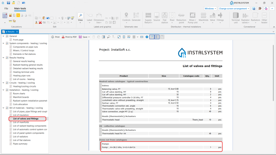
3. Pump in the Results tables.

(Optionally) Use manufacturer catalogues or sizing software to select the particular Pump model and adjust its characteristics.
Mixer / Pump unit
The Mixer / Pump unit is a block with a fixed set of elements. The functionality, defined depending on the project purposes, is achieved by selecting the appropriate Type from the Catalogues provided in the program. The unit can be neutral or from the particular manufacture.
Note: To insert the Mixer / Pump unit element, use one of the following ways:
- Place the Mixer / Pump unit element on an already drawn pipe-run using the function Insert dividing point and deleting unnecessary pipe-runs.
- Draw sequentially the pipe-runs and the Mixer / Pump unit element.
Orientation
The Orientation of the Mixer / Pump unit is selected in the Data table window from the available variants.

Use
The Use of the Mixer / Pump unit is determined in accordance with the Project scope indicated in the General data window:
- Heating,
- Heating and cooling efficiency.
Type
The Type of the Mixer / Pump unit can be chosen from the:
- Neutral catalogue Standard mixers, pump and bypass units. Depending on the use of the Mixer / Pump unit , there are three variants be selected:
- Mixing supply and return units - contain a Pump and Bypass, used to simulate mixing of the medium from the return to supply line, which leads to a decrease of the supply temperature in Radiant heating systems or an increase of the supply temperature in Radiant cooling systems, when there are also such elements like radiators or fan coils in the installation (e.g., combination of high- and low-temperature systems in a heating installation);
- Pump units - acts like Pump, ensuring the circulation of the medium. However, as a block of elements containing a Pump, it can be found in some manufacturers catalogues. Usually one or two types of real pumps are available in such blocks. This is the case where the program uses real Pump characteristics, presented Data table window;
- Units with supply to return bypass - contain only a Bypass, used to simulate mixing of the medium from the supply to return line, but without the possibility of changing the supply temperature of the medium. The input and output flow rates remain equal.
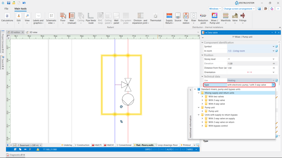
5. Mixer / Pump unit Type.
- Catalogues, provided by the particular manufacturer, selected in the General data window / Catalogues tab. For more information, see: Using catalogues and catalogues data in the project.

2D/3D view style
Presentation 2D and Presentation 3D of the Mixer / Pump unit can be:
- Detailed,
- Simplified.
The dimensions of the Mixer / Pump unit can be modified, if necessary.

Outlet temperature (mixing unit)
Outlet temperature (Heating) and Outlet temperature (Cooling) in the Mixing unit are determined automatically in accordance with the data set in the General data window for the Sources. If necessary, the values can be adjusted.

If the Mixing unit is supplying a Radiant heating systems, it serves as a low-temperature source. For more information, see: Optimization of the supply temperature of radiant systems.
In other cases, the outlet temperature of the Mixing unit is set to it's inlet temperature (no mixing assumed by default).
Results
The Mixer / Pump unit characteristics are presented after performing Calculations of Heating systems:
- In the table, displayed in the working space,
- On the element Label,
- In the Results tables,

8. Results. - In the Mixer / control unit chart for the Mixing unit. For more information, see: Mixer / control unit chart.
