Preparation of building structure: Difference between revisions
| Line 52: | Line 52: | ||
# Place the following components: ''<IS_TS id=Slab/>''. Outline of one storey is by default covered by a single slab.<br/>{{#ev:youtube|UBrQPvccvwo|900||||rel=0}} <br clear="all"/> | # Place the following components: ''<IS_TS id=Slab/>''. Outline of one storey is by default covered by a single slab.<br/>{{#ev:youtube|UBrQPvccvwo|900||||rel=0}} <br clear="all"/> | ||
# Wstawić elementy: ''<IS_TS id=Roof/>''.<br/>{{#ev:youtube|g3ratKhrlTA|900||||rel=0}} <br clear="all"/> | # Wstawić elementy: ''<IS_TS id=Roof/>''.<br/>{{#ev:youtube|g3ratKhrlTA|900||||rel=0}} <br clear="all"/> | ||
# Utworzyć dach wielospadowy.<br/>{{Info}} [[ | # Utworzyć dach wielospadowy.<br/>{{Info}} [[Preparation of building structure - Creation of roofs with different construction|Preparation of building structure - Creation of roofs with different construction]] | ||
# Wstawić elementy: ''<IS_TS id=pinNameOknoDachowe/>''<br/>{{#ev:youtube|vUm0JowDmkw|900||||rel=0}} <br clear="all"/> | # Wstawić elementy: ''<IS_TS id=pinNameOknoDachowe/>''<br/>{{#ev:youtube|vUm0JowDmkw|900||||rel=0}} <br clear="all"/> | ||
# Wstawić elementy: ''<IS_TS id=rpOtworWstropie/>''.<br/>''<IS_TS id=rpOtworWstropie/>'' można usunąć poprzez kliknięcie na [[File:Delete-ikon.png|18 px|]]<br/>{{#ev:youtube|0Tg03L0ZqRA|900||||rel=0}} <br clear="all"/> | # Wstawić elementy: ''<IS_TS id=rpOtworWstropie/>''.<br/>''<IS_TS id=rpOtworWstropie/>'' można usunąć poprzez kliknięcie na [[File:Delete-ikon.png|18 px|]]<br/>{{#ev:youtube|0Tg03L0ZqRA|900||||rel=0}} <br clear="all"/> | ||
Revision as of 12:21, 1 August 2017
| Product | InstalSystem 5 |
| Type of article | FUNCTIONALITY |
| Source for translation | IS 5.0 Beta Rev. 0.0.B33 |
Description
The article describes how building structure can be prepared and how the created structure can be verified. There are several ways the building structure can be prepared for a project. The choice of the method depends on what source data on the structure and storey plans are available and on the scope of the design to be made. If the scope of the design does not include calculation of heat losses according to standards, then rooms can be represented in the plans as polygons with no cooling partitions. Each storey constitutes a separate plan drawing sheet.
Location in program
Storeys management
- Storeys management is available in the General data window.
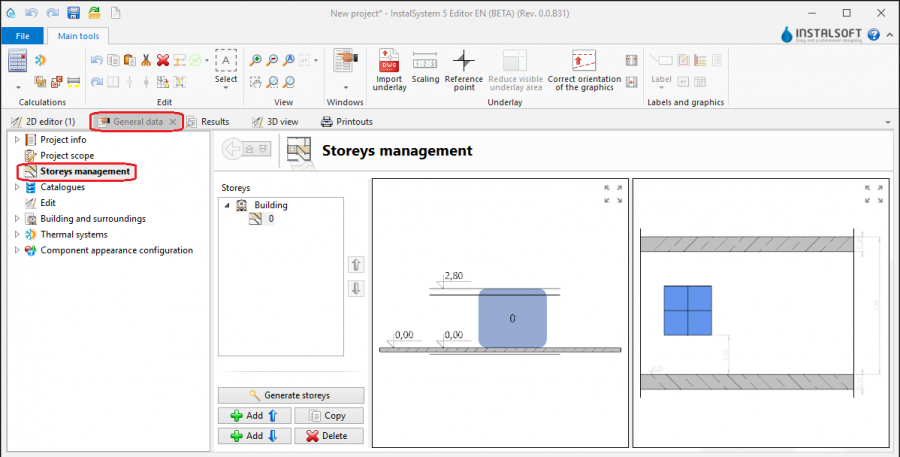
1. Storeys management

Import underlay
- Icons of components and functions related to importing underlays (base drawings) are available in the 2D Editor window on the Main tools bar in the Underlay section when the Underlay editing scope is enabled.

2. Import underlay

Building structure
- Icons of components and functions related to the building structure are available in the 2D Editor window on the Main tools bar in the Construction section when the Construction editing scope is enabled.

3. Building structure components

Computation of building structure
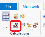
- Computation of building structure is available on the Main tools toolbar in the Calculations section.

4. Computation of building structure

Examples of use
Manual creation of building structure
Storeys
- Create the required storeys and append their data. The movie shows creation of two sets of storeys.
Underlay
Underlay (base drawing) is a two-dimensional (flat) graphical object retrieved from an external raster or vector file. The underlay itself does not provide building structure components, but it enables manual creation thereof adapted to the actual state of the building.
For more information, see: Import files
Room - manual creation of rooms
- Create a Room manually using a contour line
or by drawing a diagonal line. When a room is created by drawing a diagonal line disable the ORTO operating mode. After drawing the diagonal line complete the edition by right clicking.
Room - identification within area bordered with drawn partitions
Pomieszczenia mogą zostać utworzone automatycznie w miejscach obszarów ograniczonych krawędziami (powierzchniami) wprowadzonych przegród graficznych (ścian, stropów, dachów). W tym celu konieczne jest ręczne narysowanie w projekcie przegród graficznych i uruchomienie operacji Computation of building structure , która pozwala również na dostosowywanie przegród do narysowanej płaszczyzny dachu.
- Place a series of Wall components by entering at the start the thickness of the wall in Data table and moving the cursor along the internal edges of the walls on the underlay. In underlays retrieved from a DWG file make use of the snapping to indicated layer feature. After placing Internal walls insert External walls in similar manner.
- Place the following components: Window, Door, Opening in wall, Recess.
- Place the following components: Slab. Outline of one storey is by default covered by a single slab.
- Wstawić elementy: Roof.
- Utworzyć dach wielospadowy.
For more information, see: Preparation of building structure - Creation of roofs with different construction - Wstawić elementy: Roof window
- Wstawić elementy: Opening in slab.
Opening in slab można usunąć poprzez kliknięcie na
- Carry out Computation of building structure .
Computation of building structure launches a number of operations associated with providing a complete building structure:
- cutting away partitions by the roof plane,
- automatic identification of rooms.
Manual editing of rooms and automatic identification of walls and slabs against the background of underlay
The operation of automatic identification of walls and slabs enables creating these partitions within spaces identified between rooms included in the project and the outline of the building.
To carry out the operation:
- In the project file with previously inserted rooms, make a building outline using the 'Building outline' function.
- Optionally: if the building outline is identical on a number of storeys, enter appropriate values in the fields 'from storey' and 'to storey' in the data table of the building outline component.
- Launch interpretation of external and internal walls and slabs based on rooms and building outline using the Automatic walls, slabs and roofs function.
5.Automatic walls, slabs and roofs

Importing a complete building structure
Importing a building structure from a BIM (gbXML) compatible format
For more information, see: Import files
Importing a building structure from an InstalSystem 4 (ISB) project file
If necessary, manually correct or append the missing or incorrect components of the building structure thus obtained using the methods described above.
Verification of the correctness of building structure
Carry out the verification in the 3D view window
For more information, see: View navigation in the graphical editor