Pump and Mixing unit: Difference between revisions
Klintsevicho (talk | contribs) |
Klintsevicho (talk | contribs) No edit summary |
||
| Line 57: | Line 57: | ||
* ''<IS_TS id=MieszaczPrezentacjaSzczegolowa/>'', | * ''<IS_TS id=MieszaczPrezentacjaSzczegolowa/>'', | ||
* ''<IS_TS id=MieszaczPrezentacjaUproszczona/>''. | * ''<IS_TS id=MieszaczPrezentacjaUproszczona/>''. | ||
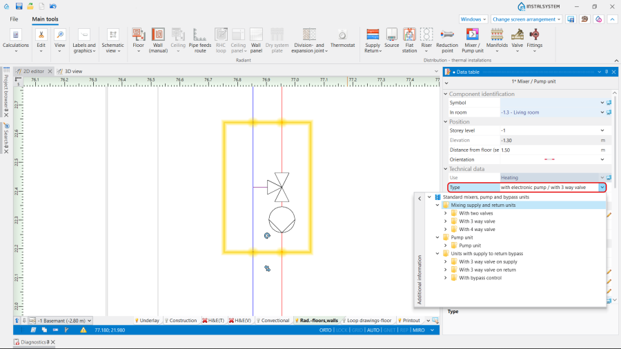
[[File:Pump and Mixer 2D 3D view.png |900 px|left|thumb|6. <IS_TS id=iNameCOReduktorTemp/> <IS_TS id=MieszaczPrezentacja2D/> and <IS_TS id=MieszaczPrezentacja3D/>.]]<br clear="all"/> | |||
The dimensions of the ''<IS_TS id=iNameCOReduktorTemp/>'' can be modified, if necessary.<br/><br/>. | |||
Revision as of 08:18, 23 December 2025
| Product | InstalSystem 5 |
| Type of article | FUNCTION AND TOOL |
| Source for translation | 2025-12-17 |
Description
The article describes the ways of using such elements as Pump and Mixer / Pump unit in Designing heating systems with convective radiators and Designing of radiant heating floor and wall installation.
Location in program
Elements Pump and Mixer / Pump unit are available in the Distribution - thermal installations tab in the Main tools menu, when Convectional, Rad.-floors,walls or Rad.-ceilings editing scope is active.

Examples of use
Pump
The Pump is inserted as a separate element on the pipe-run section.
The following data can be adjust, if necessary, in the Data table window:
- H - Pump head;
- Rotation angle.
The Pump characteristics are available in the table displayed in the working space after performing Calculations of Heating systems:

and in the Results tables:

Mixer / Pump unit
The Mixer / Pump unit is inserted as a group of elements, defined depending on the project purposes. The unit can be neutral or from the particular manufacture, selected from the Catalogues provided in the program. Note: To insert the Mixer / Pump unit element, use one of the following ways:
- Place the Mixer / Pump unit element on an already drawn pipe-run using the function Insert dividing point and deleting unnecessary pipe-runs.
- Draw sequentially the pipe-runs and the Mixer / Pump unit element.
Orientation
The Orientation of the Mixer / Pump unit is selected in the Data table window from the available variants.

Use
The Use of the Mixer / Pump unit is determined in accordance with the Project scope indicated in the General data window:
- Heating,
- Heating and cooling efficiency.
Type
The Type of the Mixer / Pump unit can be chosen from the:
- Neutral catalogue Standard mixers, pump and bypass units, provided by the program. Depending on the use of the Mixer / Pump unit , there are three variants be selected:
- Mixing supply and return units,
- Pump units,
- Units with supply to return bypass.
5. Mixer / Pump unit Type.
- Catalogues, provided by the particular manufacturer, selected in the General data window / Catalogues tab. For more information, see: Using catalogues and catalogues data in the project.

2D/3D view style
Presentation 2D and Presentation 3D of the Mixer / Pump unit can be:
- Detailed,
- Simplified.

The dimensions of the Mixer / Pump unit can be modified, if necessary.
.