Automatically generate schematic views: Difference between revisions
| Line 88: | Line 88: | ||
* A loop system is displayed as continuous series up to the last pipe-run preceding the point at which the loop is fed. <br/>[[File:SV_loop.png|900 px|left|thumb|12. Schematic view of a loop system.]]<br clear="all"/> | * A loop system is displayed as continuous series up to the last pipe-run preceding the point at which the loop is fed. <br/>[[File:SV_loop.png|900 px|left|thumb|12. Schematic view of a loop system.]]<br clear="all"/> | ||
=== | ===Schematic view - <IS_TS id=InstalacjeKanalizacyjne/>=== | ||
[[File:SV_drainage.png|900 px|left|thumb|13. | [[File:SV_drainage.png|900 px|left|thumb|13. Schematic view of <IS_TS id=InstalacjeKanalizacyjne/>.]]<br clear="all"/> | ||
===Ręczna korekta przebiegu instalacji na rozwinięciu=== | ===Ręczna korekta przebiegu instalacji na rozwinięciu=== | ||
Revision as of 18:29, 21 September 2022
| Product | InstalSystem 5 |
| Type of article | FUNCTIONS AND TOOLS |
| Source for translation | 2022-08-01 |
Description
This article describes the method of creating automatic schematic views of installations. This function is available for the following design scopes: Heating systems, Cooling systems, Water supply systems, Drainage systems. Schematic views are a form of presenting a system generated on the basis of a system model and they constitute output sheets within which some of the components can be modified. They can be edited manually, e.g. provided with additional fittings and generated again at any moment of the design process.
Schematic views are generated separately for the individual design scopes and these are independent of each other. One file can include Schematic views of the system either for all scopes or for selected scopes only. In addition each of the design scopes can have multiple schematic views.
Location in the program
- Icons of components and of functions for controlling the automatic generation of schematic views are available in the 2D editor window on the Main tools bar in the Schematic view of the individual scope:
- Convectional, Rad.-floors,walls, Rad.-ceilings editing scopes:

1. Schematic view for Convectional, Rad.-floors,walls, Rad.-ceilings editing scopes. - Water supply systems editing scope:
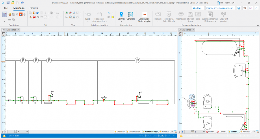
2. Schematic view for the Water supply systems editing scope. - Drainage systems editing scope:

3. Schematic view for the Drainage systems editing scope.
- Convectional, Rad.-floors,walls, Rad.-ceilings editing scopes:
- List of all Sheet type: Schematic view components generated in a project is displayed in the graphic view management window.

4. Sheet type: Schematic view in the graphic view management window.


Examples of use
Check connections
- Before executing the Generate Schematic views operation, the Check connections operation must be performed to verify the correctness of connections in the project, which is a prerequisite for the correct generation of the schematic view. The project file may contain error rank messages, but these cannot apply to system connection errors.
- Check connections is available on the Main tools bar in the Calculations group, ot it can be activated using the Shift+F2 key combination.
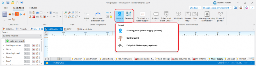
Basic components and functions for controlling automatic generation of schematic views
Starting point
This is the location in the system from which the schematic view is generated. It has to be assigned a unique symbol. Many Starting point (thermal installations) components can be inserted, and each of them generates a separate Sheet type: Schematic view ![]() . If a Starting point is deleted and Generate Schematic views is executed again, then the Sheet type: Schematic view is also deleted.
. If a Starting point is deleted and Generate Schematic views is executed again, then the Sheet type: Schematic view is also deleted.
The Starting point (thermal installations) can be placed on:
- Source
- Riser
- Pipe-run
- Pipe-runs pair.
The most important parameters of the component should be specified in the Data table window:
- Leading pipe-run - choose from the list a Pipe-run type which is to be treated as priority when generating a schematic view. This parameter is important in the case of asymmetric systems (when the supply and return pipe-runs follow separate routes). The leading pipe-runs carry marks and numbers of all junctions (tees and crosses). This field is not available for the Starting point in the Drainage systems scope.

5. Leading pipe-run. - Max. length of pipe-run to be hidden - horizontal pipe-runs or series of pipe-runs of the system the length of which is less than that specified in the field are concealed in the Sheet type: Schematic view, if they constitute the first sections connected to the system. In the case of schematic views of a Pipe-runs pair, both pipe-run types (Supply/return or Hot water/Cold water) must fulfil the Max. length of pipe-run to be hidden criterion to be concealed. This effect does not apply to a pipe-run which is the last pipe in the system. The video shows the effect of changing the value in the filed on the generated schematic view:
- Riser determines direction of schematic view - The laying direction of branches on the schematic view takes into account the viewpoint indicator of the riser. The viewing direction is indicated by a triangle near the edge of the Riser, the location of which can be changed in the 2D editor window after selecting the component. When in the Data table window of the Starting point the Riser determines direction of schematic view box is checked, the Pipe-run components connected to the riser are drawn in accordance with the following rules:
- Pipe-run components located in the <0,180) area are displayed to the right of the riser.
- Pipe-run components located in the <180,360) area are displayed to the left of the riser.
- Generate schematic views - Unchecking this box disables the generation of the schematic view during subsequent generations, e.g. new settings of the functions that control automatic generation of schematic view will not be applied. However, disabling this option does not affect the system components - refreshing is automatic, meaning that the number of system components in the model is always identical with the number of components in the schematic view. When Generate schematic views is disabled, the sheet selection list in the worksheet management window displays a padlock icon
 .
.
6. Generate schematic views. - Presented on schematic view - the scope of the generated schematic view can be controlled:
- Installation between source and risers - generates the schematic view from the indicated point to risers, excluding the risers.
- Risers - generates the schematic view from the indicated point to risers, including the risers.
- Installation behind risers - generates the schematic view from the indicated point beyond the risers to terminal units. If an installation includes stations, the schematic view is terminated at the station, if the installation includes manifolds, the schematic view is terminated at the manifold.
- Installation behind flat stations - generates the schematic view from the indicated point to the station including the installation beyond the station (in this case Installation behind risers must be checked).
- Installation behind manifold - generates the schematic view beyond the manifolds (in this case Installation behind risers must be checked)
- Automatic labels - select from the list the components for which labels are to be generated automatically in the schematic view.

7. Automatic labels. - Show room extent - when checked, the schematic view displays vertical lines representing room areas. Room labels can also be displayed, if in the Automatic labels field the Room is checked.
- Apparent shift - enables selecting the way of presenting in the schematic view of pipe-runs that are on the same level (elevation). Does not affect the elevation of the pipe-run in the model.
- Positive value - this value is added to the elevation of the supply pipe-run in the schematic view.
- Negative value - this value is subtracted from the elevation of the supply pipe-run in the schematic view.

8. Apparent shift in the schematic view of a water supply system.


This field is not available for the Starting point component within the Drainage systems scope.
The Starting point component also includes data that are associated with the design scope for which the component was inserted. More information is given further in the article:
- Starting point for the Convectional, Rad.-floors,walls, Rad.-ceilings scope: Schematic view - Heating systems.
- Starting point for the Water supply systems scope: Schematic view - Water supply systems.
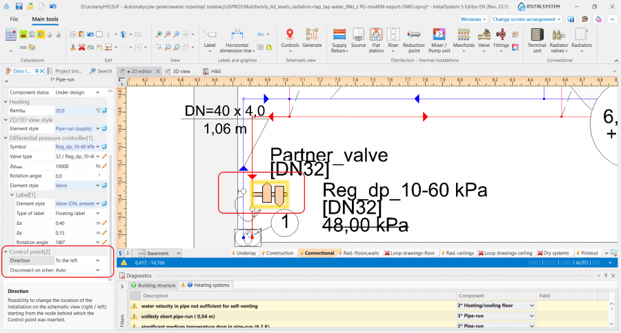
Control point
- Enables controlling the direction of generation of individual pipe feeds on the schematic view and modification of the leading route. It must be placed on the leading pipe-run. The control point changes the course of the schematic view starting from the junction beyond which it was inserted. Many Control point components can be inserted and they can be placed in a Sheet type: Schematic view or a Sheet type: Plan view.
9. Control point.

Important component parameters should be specified in the Data table window of the Pipe-run onto which the Control point component is placed:
- Direction - Specifies, for instance, whether a part of an installation (e.g.: Riser) is to be treated as placed to the right or to the left of the Source. Similarly, one can decide whether a part of the installation is to the right or to the left of a Riser. The video shows how two risers are moved in the schematic view to the left of the source.
- Disconnect on schematic view - Enables modifying the leading route in the schematic view (of the pipe-run prioritised in the generation of the schematic view), in accordance with the rules:
Possibility of correction the route of the schematic view. Control of order of presentation the parts of the installation on the schematic view:
"Yes" - during generation, the part of the installation is disconnected from the node (Tee/crosspiece) behind which the Control point is inserted
"No" - the part of the installation starting from the node behind which the Control point is inserted is not disconnected from the leading route.
Control point always acts to the right/left of the junction. The video shows the changing of the leading route in such a way as to present the critical route as the first one.
Endpoint
- The schematic view of the part of installation that is beyond the Endpoint is not generated. This part of installation is represented by a Fragment of installation. The Endpoint must have a unique symbol assigned. The video shows how a riser is removed from the schematic view.
Schematic view - Heating systems
- Starting point parameters associated with the Heating systems scope:
- Default width of mixers / control/mixing units - the value in the field defines the width of the Mixer and Control loop in the schematic view.
- Default height of mixers / control/mixing units - the value in the field defines the height of the Mixer and Control loop in the schematic view.
- How the system components are presented in the schematic view depends on the set viewing direction. The viewing direction is indicated by a triangle which is displayed after checking it in the 2D editor window.

10. Manifold viewing direction.
When placing components in a project attention must be paid to the Viewing direction of the component, as for such components as: Radiator, Mixer, Flat station or Manifold, the Control point will not change the viewing direction for these components in the schematic view. By means of the Control point the direction of unfolding of the system can be changed, but the components will always be presented in accordance with their viewing directions.
- The viewing direction of a Terminal unit can be changed instantly, which has an effect on how it is displayed in the schematic view. For more information, see: Terminal unit.

Schematic view - Water supply systems
- When the following diagnostics message:
A problem with matching cold water, hot water and circulation installations to terminal units on the "Schematic view" has occurred.
is displayed, a separate schematic view must be generated for hot water and circulation, and a separate one for cold water. - Starting point component parameters associated with the Water supply systems scope:
- Separate schematic views - when checked, the Generate a separate sheet of schematic view for cold water and separate for hot water and circulation function is enabled.

11. Generate a separate sheet of schematic view for cold water and separate for hot water and circulation .
The video shows the effect of the settings in the Separate schematic views field on generated schematic views:
- Separate schematic views - when checked, the Generate a separate sheet of schematic view for cold water and separate for hot water and circulation function is enabled.
- A loop system is displayed as continuous series up to the last pipe-run preceding the point at which the loop is fed.
12. Schematic view of a loop system.


Schematic view - Drainage systems

Ręczna korekta przebiegu instalacji na rozwinięciu
- Na Sheet type: Schematic view można wstawiać:
- Dodatkowe elementy typu Label (np.: etykiety działek). Można zmieniać również położenie wstawionych etykiet i program zachowuje ich położenie po regeneracji rozwinięcia,
- Elementy typu Valve,
- Elementy z grupy Fittings,
- Elementy z grupy Radiator valves.
- Program dostarcza szereg narzędzi pozwalających na modyfikację automatycznego rozwinięcia bądź zmianę kierunku rozwijania instalacji. W tym celu można wykorzystać:
- Możliwość zmiany kierunku patrzenia na element Riser,
- Możliwość zmiany kierunku patrzenia na element Terminal unit,
- Włączenie opcji Riser determines direction of schematic view w oknie Data table elementu Starting point.
Additional information
- Na wszystkich zakresach projektu: Heating systems, Water supply systems oraz Drainage systems elementy Starting point mają automatycznie nadawane symbole, które mogą zostać zmienione porzez narzucenie odpowiedniej wartości w polu Symbol.
- Fragmenty instalacji zawierające elementy: Wall panel i Ceiling panel nie podlegają automatycznemu generowaniu rozwinięcia i są zamieniane na elementy Fragment of installation.
- Sheet type: Schematic view utworzony w projekcie w pakiecie InstalSystem 4 jest usuwany podczas wczytywania takiego projektu do InstalSystem 5, o czym program informuje odpowiednim komunikatem diagnostyki.
- Numeracja odłączeń instalacji (węzłów) zależy od ustawienia stylu etykiety dla elementu Junction na zakładce Component appearance and descriptions configuration w oknie General data. Dla każdego z zakresów: Heating systems, Water supply systems i Drainage systems styl należy określić oddzielnie.