Heating/cooling zone: Difference between revisions
No edit summary Tag: Manual revert |
|||
| (105 intermediate revisions by 9 users not shown) | |||
| Line 1: | Line 1: | ||
<!--Case 109996--> | <!--Case 109996--> | ||
<IS_HELP id="HS89"/> | |||
{{Article table | {{Article table | ||
|commercial_product1=InstalSystem 5 | |commercial_product1=InstalSystem 5 | ||
| Line 6: | Line 7: | ||
|p4 =<!--gdy jest kolejny produkt handlowy, zamienić na->"produkt_handlowy3="--> | |p4 =<!--gdy jest kolejny produkt handlowy, zamienić na->"produkt_handlowy3="--> | ||
|category1 =InstalSystem 5#Functionalities | |category1 =InstalSystem 5#Functionalities | ||
|category_name1 = | |category_name1 =FUNCTION AND TOOL | ||
|c2 =<!--Jest kategoria -> zamienić na: "category2=" i uzupełnić link do sekcji kategorii na stronie głównej produktu--> | |c2 =<!--Jest kategoria -> zamienić na: "category2=" i uzupełnić link do sekcji kategorii na stronie głównej produktu--> | ||
|category_name2 =<!--podać nazwę kategorii--> | |category_name2 =<!--podać nazwę kategorii--> | ||
|c3 =<!--Jest kategoria -> zamienić na: "category3=" i uzupełnić link do sekcji kategorii na stronie głównej produktu--> | |c3 =<!--Jest kategoria -> zamienić na: "category3=" i uzupełnić link do sekcji kategorii na stronie głównej produktu--> | ||
|category_name3 =<!--podać nazwę kategorii "ZASTOSOWANIE"/"FUNKCJONALNOŚĆ"/...--> | |category_name3 =<!--podać nazwę kategorii "ZASTOSOWANIE"/"FUNKCJONALNOŚĆ"/...--> | ||
|version1 = | |version1 =2024-08-28 | ||
|v2 =<!--Jest wersja -> zamienić na: "version2=" i uzupełnić link do sekcji RN danego produktu--> | |v2 =<!--Jest wersja -> zamienić na: "version2=" i uzupełnić link do sekcji RN danego produktu--> | ||
|v3 =<!--Jest wersja -> zamienić na: "version2=" i uzupełnić link do sekcji RN danego produktu--> | |v3 =<!--Jest wersja -> zamienić na: "version2=" i uzupełnić link do sekcji RN danego produktu--> | ||
| Line 19: | Line 20: | ||
''<IS_TS id=strSPGCh/>'' symbolizes the area covered by one or more pipe loops of specified structural and operating parameters. It is used in the design of radiant heating and cooling systems (floors, walls and ceilings) and facilitates division into resultant ''<IS_TS id=strPGCh/>'' components. | ''<IS_TS id=strSPGCh/>'' symbolizes the area covered by one or more pipe loops of specified structural and operating parameters. It is used in the design of radiant heating and cooling systems (floors, walls and ceilings) and facilitates division into resultant ''<IS_TS id=strPGCh/>'' components. | ||
==Videos related to the article== | |||
<br/>{{#ev:youtube|y3O2KyYPLpg|450||||rel=0}} <br clear="all"/> | |||
==Location in program== | ==Location in program== | ||
| Line 25: | Line 29: | ||
==Examples of use== | ==Examples of use== | ||
===Inserting into rooms=== | ===Inserting into rooms=== | ||
====Inserting a | ====Inserting a <IS_TS id=iNameOPStrefaPodlogGrzejnych/>==== | ||
{{#ev:youtube|wonqVv7UXf4|900||||rel=0}} | {{#ev:youtube|wonqVv7UXf4|900||||rel=0}} | ||
====Inserting a | </br> | ||
====Inserting a <IS_TS id=iNameOPStrefaScianGrzejnych/>==== | |||
{{#ev:youtube|YkgckD45Zds|900||||rel=0}} | {{#ev:youtube|YkgckD45Zds|900||||rel=0}} | ||
====Inserting a | </br> | ||
====Inserting a <IS_TS id=iNameOPStrefaSufirowGrzejnych/>==== | |||
{{#ev:youtube|-0V0qEsweww|900||||rel=0}} | {{#ev:youtube|-0V0qEsweww|900||||rel=0}} | ||
</br> | |||
===Openings in heating-cooling areas zone=== | |||
* The program is provided with a ''<IS_TS id=rpCuttingHoles/>'' operation which ''<IS_TS id=rpCuttingHolesHint/>'' The operation is accessible in the ''2D Editor'' window on the ''<IS_TS id=NarzedziaGlowne/>'' bar in section ''<IS_TS id=NazwaZakladkiOP/>'' for the enabled ''<IS_TS id=ScopeInstalacjePodlogoweIScienneShort/>'' or ''<IS_TS id=ScopeInstalacjeSufitoweShort/>'' editing scopes.</br>[[File:Cutting holes.png |900 px|left|thumb|6. <IS_TS id=rpCuttingHoles/> operation.]]<br clear="all"/> | |||
* Loops are arranged properly around cut out area. Once the hole has been cut out, it is necessary to perform the calculations again in order to correctly determine the ''<IS_TS id=strpnGrzejPowEfektywna/>'' and arrange the loop bypassing the cut-out area. </br>{{#ev:youtube|-CTThPErgJM|900||||rel=0}}<br clear="all"/> | |||
* Fragment of the ''<IS_TS id=iNameOPStrefaPodlogGrzejnych/>''/''<IS_TS id=iNameOPStrefaSufirowGrzejnych/>'' component is automatically cut out where the ''<IS_TS id=rpOtworWstropie/>'' component is placed in the structural slab, when the ''<IS_TS id=iNameOPStrefaPodlogGrzejnych/>''/''<IS_TS id=iNameOPStrefaSufirowGrzejnych/>'' was inserted automatically. </br>{{#ev:youtube|x8JRbvyGQ8c|900||||rel=0}}<br clear="all"/> | |||
===Dividing a <IS_TS id=strSPGCh/>=== | |||
Tools are available that enable dividing: | |||
* ''<IS_TS id=strSPGCh/>'' components into ''<IS_TS id=strSPGCh/>'' components, | |||
* ''<IS_TS id=strSPGCh/>'' components into ''<IS_TS id=strPGCh/>'' components. | |||
Enables differentiating structural data (e.g. cladding), operating or functional parameters within one room. The parameters of ''<IS_TS id=strSPGCh/>'' components are inherited upon division from the divided surface zone. | |||
</br> | |||
====Automatic division along edges into specified number==== | |||
May be effected using vertical, horizontal or indicated division lines.<br/>{{#ev:youtube|bkMTKN8-UY8|900||||rel=0}}<br clear="all"/> | |||
====Manual division==== | |||
Manual division of the ''<IS_TS id=strSPGCh/>'' can be realized using the group of commands ''<IS_TS id=rpPodzialIdylatacja/>'':<br/>[[File:Dividing H-C zones.png|900 px|left|thumb|7. <IS_TS id=rpPodzialIdylatacja/>]]<br clear="all"/> | |||
* ''<IS_TS id=rpPodzialPowierzchniBezDylatacji/>'' - ''<IS_TS id=rpPodzialPowierzchniBezDylatacjiHint/>'';<br/>{{#ev:youtube|0FOZLCQ4UaM|900||||rel=0}}<br clear="all"/> | |||
* ''<IS_TS id=PodzialPowierzchniZDylatacja/>'' - ''<IS_TS id=PodzialPowierzchniZDylatacjaHint/>'';<br/>{{#ev:youtube|-9F4S5cBIZc|900||||rel=0}}<br clear="all"/> | |||
* ''<IS_TS id=LiniaPodzialuPGCH/>'' - ''<IS_TS id=rpLiniaPodzialuPGCHHint/>'';<br/>{{#ev:youtube|l6NjFgN6qts|900||||rel=0}}<br clear="all"/> | |||
* ''<IS_TS id=rpCuttingHoles/>'' - ''<IS_TS id=rpCuttingHolesHint/>'' {{Info}} [[Heating/cooling_zone#Openings_in_heating-cooling_areas_zone | Openings in heating-cooling areas zone]];</br> | |||
* ''<IS_TS id=DylatacjaCaption/>'' - ''<IS_TS id=rpDylatacjaHint/>''; | |||
* ''<IS_TS id=rpDylatacjaRecznie/>'' - ''<IS_TS id=rpDylatacjaRecznieHint/>''. | |||
====Shape adjustment==== | |||
* By relocating characteristic points on edges.<br/>These are activated by clicking the label of ''<IS_TS id=strSPGCh/>'' component if: | |||
** it was inserted into a room as a polygon, | |||
** it was divided before. | |||
* Using the ''<IS_TS id=rpPodzialPowierzchniBezDylatacji/>'' function.</br>{{#ev:youtube|AJ98p1A-r0c|900||||rel=0}}<br clear="all"/> | |||
===Functional change=== | ===Functional change=== | ||
| Line 40: | Line 80: | ||
* ''<IS_TS id=vltpgSlepaBezRur/>'' - symbolizes one ''<IS_TS id=strPGCh/>'' component with no pipe loop. ''<IS_TS id=strPGCh/>'' does not provide heating/cooling, but its structural parameters are like those of other ''<IS_TS id=strPGCh/>'' components in the room. | * ''<IS_TS id=vltpgSlepaBezRur/>'' - symbolizes one ''<IS_TS id=strPGCh/>'' component with no pipe loop. ''<IS_TS id=strPGCh/>'' does not provide heating/cooling, but its structural parameters are like those of other ''<IS_TS id=strPGCh/>'' components in the room. | ||
* ''<IS_TS id=vltpgWieloobwodowa/>'' - symbolizes one ''<IS_TS id=strPGCh/>'' component covered by multiple parallel pipe loops of identical length. | * ''<IS_TS id=vltpgWieloobwodowa/>'' - symbolizes one ''<IS_TS id=strPGCh/>'' component covered by multiple parallel pipe loops of identical length. | ||
[[File: | * ''<IS_TS id=vltpgZOgrTempPowr/>'' - symbolizes one ''<IS_TS id=strPGCh/>'' component fed directly from a high-parameter network. {{Info}} [[Heating floor with return temperature limiter]]. | ||
* ''<IS_TS id=vltpgZOgrTempPowrGrzejnika/>'' - symbolizes one ''<IS_TS id=strPGCh/>'' component fed from the return line of a convection heater. {{Info}} [[Heating floor with return temperature limiter]].</br>[[File:H_C_zone_type_new.png|900 px|left|thumb|2. <IS_TS id=strpnPGTypPG/>]]<br clear="all"/> | |||
=== | ===Changing operating parameters=== | ||
* | * A substantial number of parameters is appended automatically by copying data from ''<IS_TS id=rsDanogi/>''.<br/>Changing copied parameters: {{Info}} [[General data#Default data of systems under design|General data]]. | ||
* | * Selected modifiable parameters:</br>[[File:SPGCh-operating-parameters.png|900 px|left|thumb|3. Operating parameters]]<br clear="all"/> | ||
[[File:SPGCh-operating-parameters.png|900 px|left|thumb|3. Operating parameters]]<br clear="all"/> | |||
=== | ===Changing structural parameters=== | ||
* | * A substantial number of parameters is appended automatically by copying data from ''<IS_TS id=rsDanogi/>''.<br/>Changing copied parameters: {{Info}} [[General data#Default data of systems under design|General data]]. | ||
* | * Selected modifiable parameters:</br>[[File:SPGCh-construction-parameters.PNG|900 px|left|thumb|4. Construction parameters]]<br clear="all"/> | ||
[[File:SPGCh-construction-parameters.PNG|900 px|left|thumb|4. Construction parameters]]<br clear="all"/> | {{#ev:youtube|LE2jnUuz3tk|900||||rel=0}}<br clear="all"/> | ||
{{#ev:youtube|LE2jnUuz3tk|900||||rel=0}} | |||
=== | ===Defining a Peripheral zone=== | ||
{{#ev:youtube|ckmdsGUaXGk|900||||rel=0}} | {{#ev:youtube|ckmdsGUaXGk|900||||rel=0}}<br clear="all"/> | ||
=== | ===Dividing a <IS_TS id=strSPGCh/> into <IS_TS id=strPGCh/> components=== | ||
For the sake of ease of design, it is recommended to let the program carry out the division, required to maintain operating parameters within limits (see below). | |||
==== | ====Division criteria==== | ||
Division is done based on one of the two criteria: | |||
=== | * ''<IS_TS id=SPG_PartitionCriterionDeltaP/>'' (''<IS_TS id=strs_expidISFPowGrzejnaMaxDP/>'')<br/>Upon selecting this criterion, the division is into ''<IS_TS id=strPGCh/>'' components with identical pressure drop (permissible 5% deviation between pipe lengths in a loop). | ||
* ''<IS_TS id=SPG_PartitionCriterionArea/>''<br/>Upon selecting this criterion, the division is into ''<IS_TS id=strPGCh/>'' components with identical surface area (including pipe feeds) (permissible 5% deviation between surface areas). | |||
The following parameters are observed in the division criteria: | |||
* ''<IS_TS id=SPG_PartitionCriterionDeltaP/>'', | |||
* ''Maximum permissible coil length in loop'' (''<IS_TS id=strMaxDlugoscPetliSymbol/>''), | |||
* ''Division orientation'' of component ''<IS_TS id=strSPGCh/>'' into ''<IS_TS id=strPGCh/>'' components. | |||
If the ''<IS_TS id=strSPGCh/>'' component has a ''Peripheral zone'' defined, then additional conditions are taken into account: | |||
* Arrangement of defined ''Peripheral zones'' in ''<IS_TS id=strSPGCh/>'', | |||
* Form of effecting the ''Peripheral zone''. | |||
Automatic division of a ''<IS_TS id=strSPGCh/>'' into ''<IS_TS id=strPGCh/>'' components is disabled by: | |||
* Switching of ''<IS_TS id=iNameOPStrefaPrzylaczy/>'' into manual mode.<br/>{{Info}} [[Editing pipe feeds in a radiant system]] | |||
* Manual connection of a ''Pipe-run pair'' to the ''<IS_TS id=strSPGCh/>''. The program assumes that inside a ''<IS_TS id=strSPGCh/>'' there is only one ''<IS_TS id=strPGCh/>''.<br/>{{Info}} [[Editing pipe feeds in a radiant system]] | |||
* Manual indication of the dividing line. | |||
* Modification in the ''<IS_TS id=ShowInteractiveCalculationWindow/>'' window of parameters determined by the program: ''<IS_TS id=SpacingVariants/>'' and/or ''<IS_TS id=strDeltaThetaLong/>''. | |||
* Disabling the ''<IS_TS id=ModeAutoDivideHeatingZone/>'' function in the ''<IS_TS id=DataEditorTable/>'' window. | |||
==== | ====Changing division orientation==== | ||
{{#ev:youtube|avbEvEgGvVg|900||||rel=0}}<br clear="all"/> | {{#ev:youtube|avbEvEgGvVg|900||||rel=0}}<br clear="all"/> | ||
==== | ====Manual indication of the dividing line==== | ||
Manual indication of the dividing line is possible when the automatic division of ''<IS_TS id=strSPGCh/>'' into ''<IS_TS id=strPGCh/>'' components is disabled, which is indicated by the message: ''<IS_TS id=HeatingZoneSwitchConnectionModeToManualConfirmation/>''. | |||
{{#ev:youtube|ew4NJy-8hcE|900||||rel=0}}<br clear="all"/> | {{#ev:youtube|ew4NJy-8hcE|900||||rel=0}}<br clear="all"/> | ||
==== | |||
====Modifying the dividing line after automatic division==== | |||
Modification of the automatic division line disables the automatic division of ''<IS_TS id=strSPGCh/>'' into ''<IS_TS id=strPGCh/>'' components during subsequent calculations. | |||
When automatic division is enabled, the handles on the edges of ''<IS_TS id=strPGCh/>'' componetns are not displayed. | |||
{{#ev:youtube|ojz39H4g62g|900||||rel=0}}<br clear="all"/> | {{#ev:youtube|ojz39H4g62g|900||||rel=0}}<br clear="all"/> | ||
==Additional information== | ==Additional information== | ||
=== | ===Differences in relation to version 4=== | ||
# ''<IS_TS id=strSPGCh/>'' | # ''<IS_TS id=strSPGCh/>'' in ''InstalSystem 5'' differs from similar components in ''InstalSystem 4'', because: | ||
#* | #* is an area inside which ''<IS_TS id=strPGCh/>'' components are created, similar to those in version 4, | ||
#* | #* it is not possible to delete individual ''<IS_TS id=strPGCh/>'' components when editing a project, | ||
#* | #* peripheral zone can only be defined for the ''<IS_TS id=strSPGCh/>'' component. | ||
# | # Depending on the location in a room, it is available in one of the editing scopes: | ||
#* ''<IS_TS id=ScopeInstalacjePodlogoweIScienneShort/>'', | #* ''<IS_TS id=ScopeInstalacjePodlogoweIScienneShort/>'', | ||
#* ''<IS_TS id=ScopeInstalacjeSufitoweShort/>''. | #* ''<IS_TS id=ScopeInstalacjeSufitoweShort/>''. | ||
{|class="wikitable" style="width: 800px; margin: 0 auto;" | |||
!If you have any comments on this article, please send us a short message at ''info@instalsoft.com''. | |||
|} | |||
[[Category:InstalSystem 5]] | [[Category:InstalSystem 5]] | ||
[[Category: | [[Category:FUNCTION AND TOOL]] | ||
<!-- Do not write text below this tag --> | |||
<br class="iwlinks"/>[[pl:Strefa powierzchni grzewczo-chłodzących|Strefa powierzchni grzewczo-chłodzących]][[fa:مناطق گرمایش/سرمایش|مناطق گرمایش/سرمایش]][[zh-cn:供热/供冷区|供热/供冷区]][[bg:Отоплителна/охладителна зона|Отоплителна/охладителна зона]] | |||
Latest revision as of 23:03, 12 June 2026
| Product | InstalSystem 5 |
| Type of article | FUNCTION AND TOOL |
| Source for translation | 2024-08-28 |
Description
Heating/Cooling Zone symbolizes the area covered by one or more pipe loops of specified structural and operating parameters. It is used in the design of radiant heating and cooling systems (floors, walls and ceilings) and facilitates division into resultant Heating-cooling surface components.
Location in program
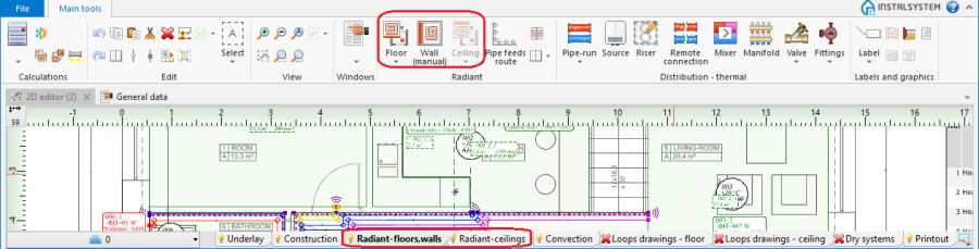
- Heating/Cooling Zone icons are located in the 2D Editor window on the Main tools toolbar, section Radiant for editing scopes Rad.-floors,walls or Rad.-ceilings.
1. Heating/Cooling Zone

Examples of use
Inserting into rooms
Inserting a Heating/Cooling Floor Zone
Inserting a Heating/Cooling Wall Zone
Inserting a Heating/Cooling Ceiling Zone
Openings in heating-cooling areas zone
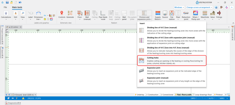
- The program is provided with a Cutting holes operation which Enables cutting an opening in the heating or cooling floor/ceiling for poles, columns, kitchen islands, etc. The operation is accessible in the 2D Editor window on the Main tools bar in section Radiant for the enabled Rad.-floors,walls or Rad.-ceilings editing scopes.
6. Cutting holes operation. - Loops are arranged properly around cut out area. Once the hole has been cut out, it is necessary to perform the calculations again in order to correctly determine the Effect. area and arrange the loop bypassing the cut-out area.
- Fragment of the Heating/Cooling Floor Zone/Heating/Cooling Ceiling Zone component is automatically cut out where the Opening in slab component is placed in the structural slab, when the Heating/Cooling Floor Zone/Heating/Cooling Ceiling Zone was inserted automatically.

Dividing a Heating/Cooling Zone
Tools are available that enable dividing:
- Heating/Cooling Zone components into Heating/Cooling Zone components,
- Heating/Cooling Zone components into Heating-cooling surface components.
Enables differentiating structural data (e.g. cladding), operating or functional parameters within one room. The parameters of Heating/Cooling Zone components are inherited upon division from the divided surface zone.
Automatic division along edges into specified number
May be effected using vertical, horizontal or indicated division lines.
Manual division
Manual division of the Heating/Cooling Zone can be realized using the group of commands Division and expansion joint:

- Dividing line of H/C Zone (manual) - Allows you to divide the heating/cooling zone into more zones with the indication of the cutting edge;
- Dividing line of H/C Zone with expansion joint (manual) - Allows you to divide the heating/cooling zone into more zones with the application of expansion joint on cutting edge;
- Dividing line of H/C Zone into H/C Area (manual) - Allows you to indicate manually the course of the edge of the division of the heating/cooling zone into heating/cooling areas;
- Cutting holes - Enables cutting an opening in the heating or cooling floor/ceiling for poles, columns, kitchen islands, etc. For more information, see: Openings in heating-cooling areas zone;
- Expansion joint - Allows you to insert an expansion joint at the indicated edge of the heating/cooling zone;
- Expansion joint (manual) - Allows you to insert an expansion joint of any length on the edge of the heating/cooling zone.
Shape adjustment
- By relocating characteristic points on edges.
These are activated by clicking the label of Heating/Cooling Zone component if:- it was inserted into a room as a polygon,
- it was divided before.
- Using the Dividing line of H/C Zone (manual) function.
Functional change
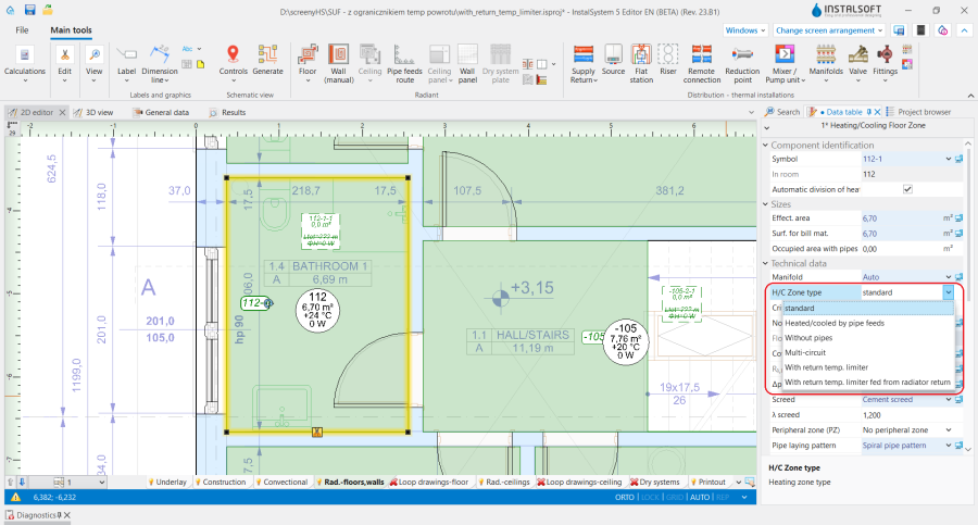
H/C Zone type:
- Standard - symbolizes one or more Heating-cooling surface components, each of which is covered by a single pipe loop.
- Heated/cooled by pipe feeds - symbolizes one Heating-cooling surface component, which has no pipe loop assigned to it. Energy is supplied only by feed pipes that run across to other Heating-cooling surface components.
- Without pipes - symbolizes one Heating-cooling surface component with no pipe loop. Heating-cooling surface does not provide heating/cooling, but its structural parameters are like those of other Heating-cooling surface components in the room.
- Multi-circuit - symbolizes one Heating-cooling surface component covered by multiple parallel pipe loops of identical length.
- With return temp. limiter - symbolizes one Heating-cooling surface component fed directly from a high-parameter network. For more information, see: Heating floor with return temperature limiter.
- With return temp. limiter fed from radiator return - symbolizes one Heating-cooling surface component fed from the return line of a convection heater. For more information, see: Heating floor with return temperature limiter.
2. H/C Zone type

Changing operating parameters
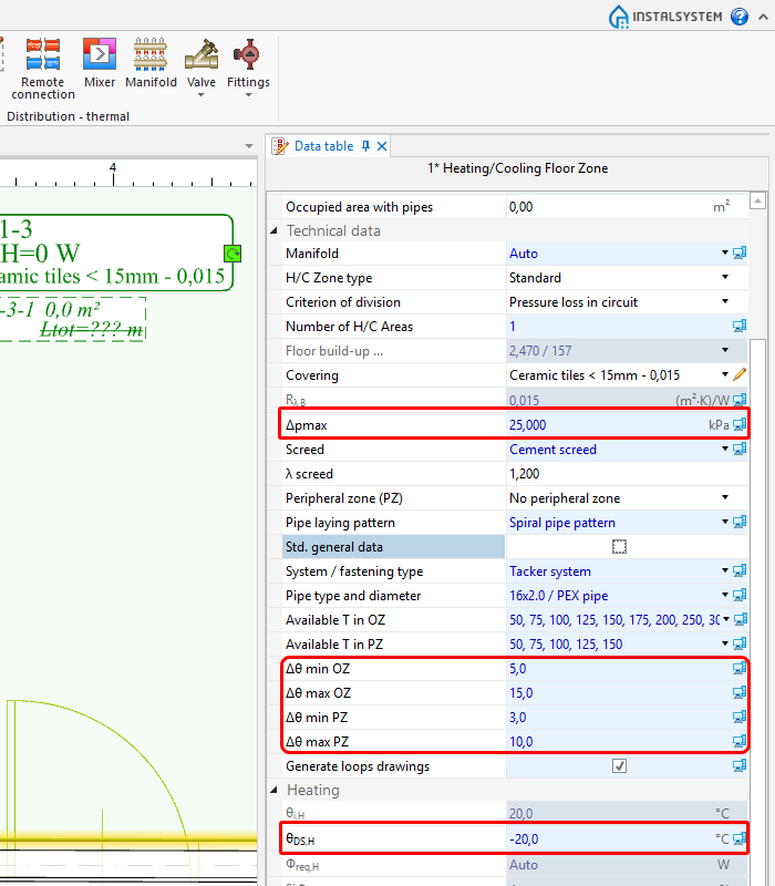
- A substantial number of parameters is appended automatically by copying data from General data.
Changing copied parameters: For more information, see: General data. - Selected modifiable parameters:
3. Operating parameters

Changing structural parameters
- A substantial number of parameters is appended automatically by copying data from General data.
Changing copied parameters: For more information, see: General data. - Selected modifiable parameters:
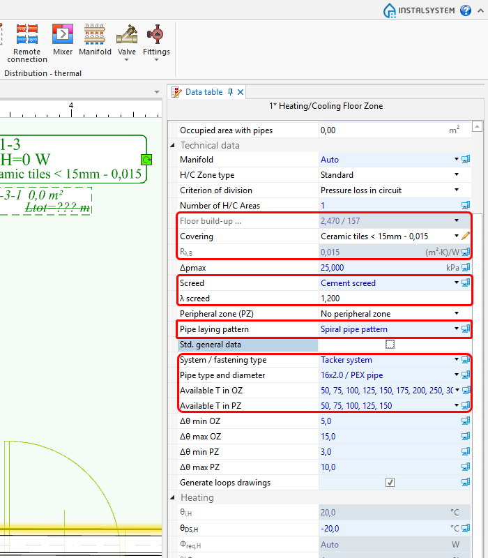
4. Construction parameters

Defining a Peripheral zone
Dividing a Heating/Cooling Zone into Heating-cooling surface components
For the sake of ease of design, it is recommended to let the program carry out the division, required to maintain operating parameters within limits (see below).
Division criteria
Division is done based on one of the two criteria:
- Equal pressure losses (Δpmax)
Upon selecting this criterion, the division is into Heating-cooling surface components with identical pressure drop (permissible 5% deviation between pipe lengths in a loop). - Equal areas
Upon selecting this criterion, the division is into Heating-cooling surface components with identical surface area (including pipe feeds) (permissible 5% deviation between surface areas).
The following parameters are observed in the division criteria:
- Equal pressure losses,
- Maximum permissible coil length in loop (Max. L),
- Division orientation of component Heating/Cooling Zone into Heating-cooling surface components.
If the Heating/Cooling Zone component has a Peripheral zone defined, then additional conditions are taken into account:
- Arrangement of defined Peripheral zones in Heating/Cooling Zone,
- Form of effecting the Peripheral zone.
Automatic division of a Heating/Cooling Zone into Heating-cooling surface components is disabled by:
- Switching of Pipe feeds route into manual mode.
For more information, see: Editing pipe feeds in a radiant system - Manual connection of a Pipe-run pair to the Heating/Cooling Zone. The program assumes that inside a Heating/Cooling Zone there is only one Heating-cooling surface.
For more information, see: Editing pipe feeds in a radiant system - Manual indication of the dividing line.
- Modification in the Interactive radiant systems calculations window of parameters determined by the program: and/or Temp. diff. supply-return.
- Disabling the Automatic division of heating zone function in the Data table window.
Changing division orientation
Manual indication of the dividing line
Manual indication of the dividing line is possible when the automatic division of Heating/Cooling Zone into Heating-cooling surface components is disabled, which is indicated by the message: Manual indication of division line disables automatic division of H/C Zone into H/C Areas.
Would you like to continue?.
Modifying the dividing line after automatic division
Modification of the automatic division line disables the automatic division of Heating/Cooling Zone into Heating-cooling surface components during subsequent calculations. When automatic division is enabled, the handles on the edges of Heating-cooling surface componetns are not displayed.
Additional information
Differences in relation to version 4
- Heating/Cooling Zone in InstalSystem 5 differs from similar components in InstalSystem 4, because:
- is an area inside which Heating-cooling surface components are created, similar to those in version 4,
- it is not possible to delete individual Heating-cooling surface components when editing a project,
- peripheral zone can only be defined for the Heating/Cooling Zone component.
- Depending on the location in a room, it is available in one of the editing scopes:
- Rad.-floors,walls,
- Rad.-ceilings.
| If you have any comments on this article, please send us a short message at info@instalsoft.com. |
|---|