Hydraulic control loop
| Product | InstalSystem 5 |
| Type of article | FUNCTION AND TOOL |
| Source for translation | 2026-06-15 |
Description
Hydraulic control loop is the element used to hydraulically balance and regulate (qualitatively or quantitatively) the thermal efficiency of the end receiver (e.g., fan-coil or cooling beam). The article describes the ways of applying the element in the program.
Hydraulic control loops
Catalogues of hydraulic control loops
The direct use of components such as Pump and Mixer is described in a separate article Pump and Mixer.
Location in program
Hydraulic control loop is presented in the program as a separate module, the availability of which is visible in the InstalSystem 5.5 Manager / Help tab / list of Modules available in current licence configuration:

To use the Hydraulic control loop element, the corresponding catalogues should be selected and added to the project in the General data window / Catalogues tab. For more information, see: Selecting catalogues for the project.

The element can be placed on the drawing when Convectional, Rad.-floors,walls or Rad.-ceilings editing scope is active:
- clicking the icon Hydraulic control loop in the Distribution - thermal installations tab in the Main tools menu:
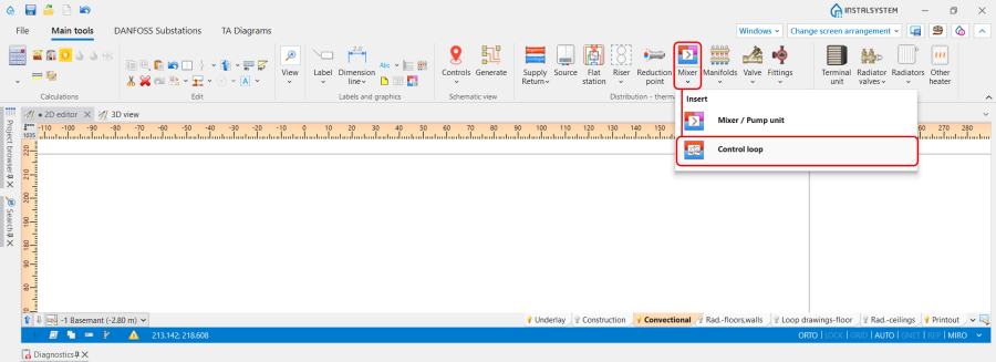
3. Hydraulic control loop icon. - clicking the icon with schemes presented by the particular producers:
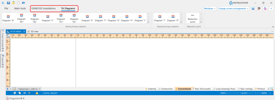
4. Hydraulic control loop schemes.

Examples of use
Hydraulic control loop is a prefabricated block of grouped elements and is not graphically editable. May include a pump, balancing valves, control valves and overflow-relief valve. Allows the use of valves and fittings only from a list of items, suitable for use in a given location, in a configuration precisely defined by producers.
Orientation
The Orientation of the Hydraulic control loop is selected in the Data table window from the available variants.

Use
The Use of the Hydraulic control loop is determined in accordance with the Project scope indicated in the General data window:
- Heating,
- Cooling,
- Heating and cooling efficiency.
Type
The Type of the Hydraulic control loop сan be chosen from the catalogues, provided by the particular manufacturers, selected in the General data window / Catalogues tab. For more information, see: Using catalogues and catalogues data in the project.
The selection is available in the Data table window and on the Ribbon. In addition, the Ribbon icons provide a visualization of the proposed schemas for the arrangement of the Hydraulic control loop components.

2D/3D view style
Presentation 2D and Presentation 3D of the Hydraulic control loop can be:
- Detailed,
- Simplified.
The dimensions of the Hydraulic control loop can be modified, if necessary.

Results
The Hydraulic control loop data is presented after performing Calculations of Heating systems/Cooling systems:
- In the hint, displayed after placing the mouse cursor on the element,
- In the element Label,
- In the Results tables,
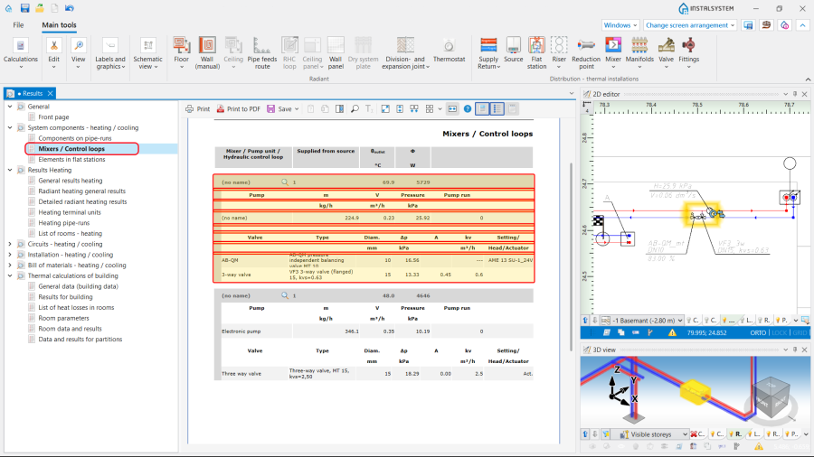
8. Results. - In the Mixer / control unit chart. For more information, see: Mixer / control unit chart.
