Design of water installation - basics
| Product | InstalSystem 4 |
| Type of article | DESIGN APPLICATION |
| Content up-to-date for version | IS 4.13 |
Range of lesson
The following lesson demonstrates how to make the water supply system in Instal-san T.
The installation is located in a two-storey, single family building without basement.
Modules and program configuration
- Instal-san T allows to make the project of water supply system.
- catalogs for selecting types:
- pipes, fittings and the connections systems
- insulation
- fittings and valves
- batteries, taps and ceramic appliances
Inital state
The file in an initial state takes into account the graphical presentation of the ground and the floor, shown in two separate sheets.
- The file in an initial state:Instal-san construction, .ISB
More about how to download the file: How to calculate a file using a package configuration other than the one under which the file was created.
- The file in an initial state:Instal-san construction, .ISB
Steps to perform
Running application and configuration of basic project data
- Run the program Instal-san T.
- Load the file with the prepared structure of the building.
- Start the Worksheets management window and add a sheet which will be schematic view of installation.
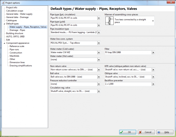
- Go to editing Window Project options (F7).
- Make a general overview in Project options of the data in terms of tabs:
- "General data - Water supply"
- "Catalogues"
- "Default types" / "Water supply - Pipes, Receptors, Valves" and make changes, if expected data are different from the default data visible after starting the program.
1. General data

Inserting taps
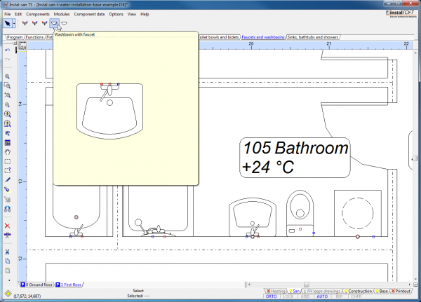
Go to the San editing scope, then insert water outlet points using one of the available methods:
- Insert complete set of components:
- From the toolbar, select a ready set of elements created by the sanitary utensil and the tap, available in different variants.

2. Sanitary utensils with taps
- From the toolbar, select a ready set of elements created by the sanitary utensil and the tap, available in different variants.
- Insert a separate sanitary utensil and tap:
- From the toolbar, select the sanitary utensil in the basic variant and the tap in the basic variant.
3. Sanitary utensils 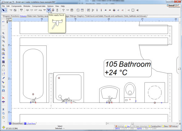
4. Taps
- From the toolbar, select the sanitary utensil in the basic variant and the tap in the basic variant.


If there is no suitable drawing version of a faucet, select the appropriate type in the "Faucet type" field in the component data table. In the "Water outlet point" the required calculation parameters can be indicated without changing the component drawing.
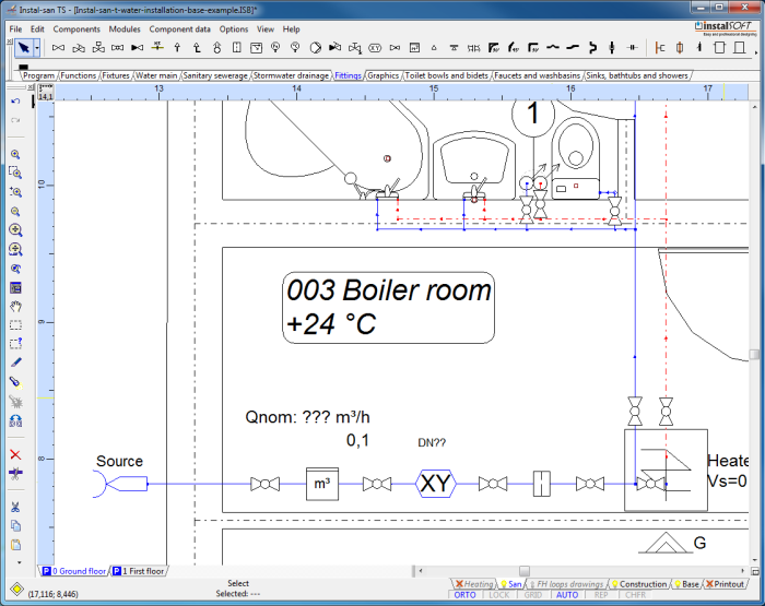
Inserting water source and heater
- Insert source of utility water in the plan sheet.
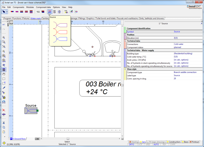
5. Source - If hot water is prepared at the site, insert heater in the plan sheet.
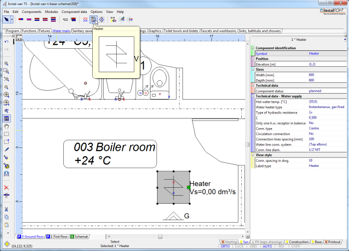
6. Heater


Inserting water stacks
- Insert water stacks feeding water to terminal units on each storey. Insert circulation stacks also, if these are included in the design.
- Assign names to the stacks.
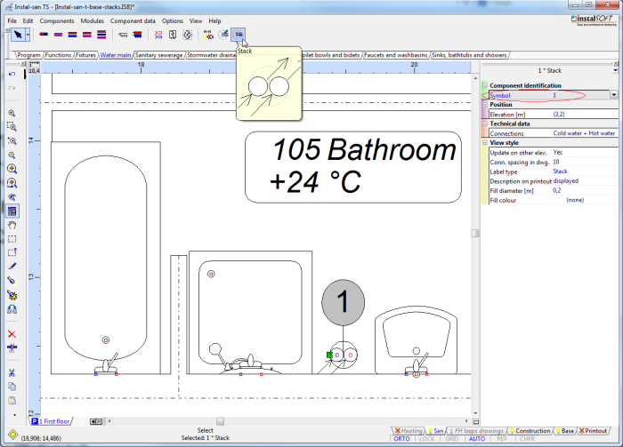
7. Water stack

Inserting utility water pipe-runs
- On each storey insert UCW and UHW pipe-runs between source and stacks and between stacks and terminal units.
- Do not connect the inserted pipe-runs to terminal units. In order to avoid automatic connection, terminate the pipe-runs at a certain distance from the faucet, holding the Shift key, if necessary.
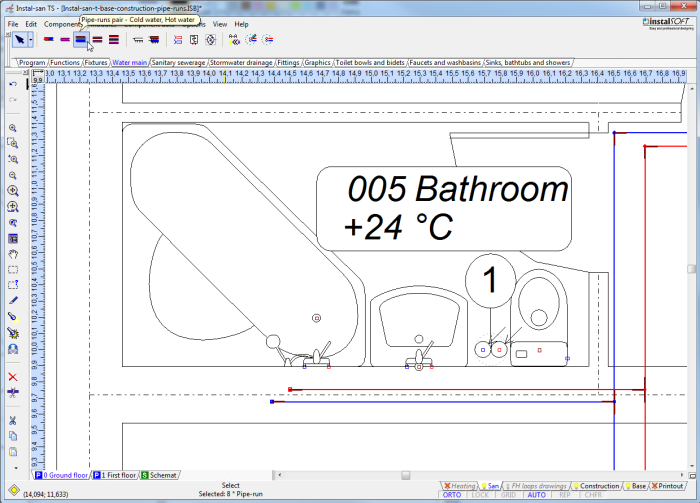
8. Utility water pipe-runs

Connecting terminal units
- Mark fragment of the system to include terminal units and pipe-runs to be connected, then press Shift+Ctrl+A or select "Automatically connect terminal units" in the Components menu.
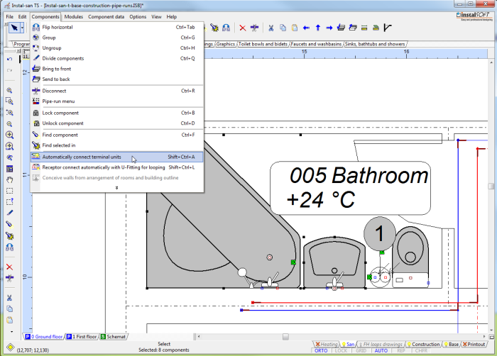
9. Connecting terminal units - Confirm automatic deletion of unnecessary pipe ends.
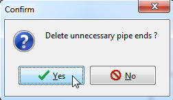
10. Delete unnecessary pipe ends 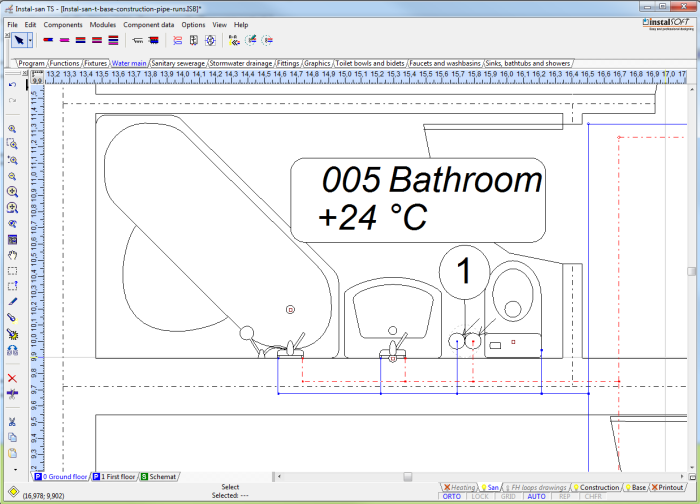
11. Connected terminal units - If there is circulation system in the project, the circulation pipe should be connected near the terminal unit that is most distant from the source.


Inserting fitings
- Insert the required pieces of conduit fittings:
- isolating valves
- backflow preventer
- water meter
- pipe fittings
12. Fixtures

Executing calculations
- Verify the correctness of connections by pressing Shift+F2.
- If connections of all components are correct, run calculations by pressing F10 or by clicking the appropriate icon.

- Study the displayed diagnostic messages. These messages can be classified into three categories:
- errors - messages of utmost importance, there are two types of errors: critical errors that cause interruption of calculations, and errors that do not cause interruption of the calculations, but in the case of their occurrence results may not be reliable. Errors that cause interruptions in calculations have to be eliminated because their occurrence will not allow the project to be recalculated.
- warnings - these messages are less important than errors and they do not interrupt calculations or the display of results. Warnings are most often associated with data or results that do not need to change but are probably incorrect, and therefore the content of the warnings should always be checked.
- hints - these messages are only intended to remind of or to draw attention to certain data or results. Like warnings, hints do not interrupt calculations or the display of results.
Project modification and recalculation
- The areas where modifications are made most often:
- Components (add, move, delete, edit values in component data tables),
- General data (edit data specified for default settings),
- Calculation options (modify basic options that affect calculations).
- After making changes calculations can be run again.
Print and export results
Drawings and tables of results can be printed or exported to various file formats, e.g.: AutoCad DWG/DXF, JPEG, PaintBrush, Windows Bitmap (drawings) or MS-Excel (tables).
Final state
The following is a set of files:
Project file, Instal-san T EN: Instal-san result file, .ISB
More about how to download the file: How to calculate a file using a package configuration other than the one under which the file was created.