Appending drawings with radiant system loops
| Product | InstalSystem 5 |
| Type of article | FUNCTION AND TOOL |
| Source for translation | 2022-08-30 |
Description
The Heating-cooling surface component (floors and ceilings) can be appended with drawings of loops. Drawings generated automatically by the program are refreshed each time the project is recalculated. It is possible to modify or append them and loops can be drawn manually. Manual editing is recommended at the final stage of design.
Webinars
We encourage you to see the video from our webinars presenting the possibilities of using the function described in this article:
Location in the program
- General data - automatic generation of loops can be enabled for all components by selecting the Generate loops drawings checkbox.
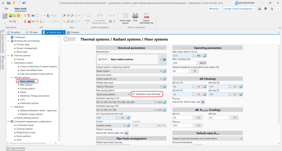
1. Generate loops drawings - Data table for component Heating/Cooling Floor Zone, when working in the Rad.-floors,walls/Rad.-ceilings editing range, enables:
- automatic generation of loops by selecting the Generate loops drawings checkbox; loop generation can be disabled here for a selected component when this checkbox is selected in General data,
- selection of pipe laying pattern.
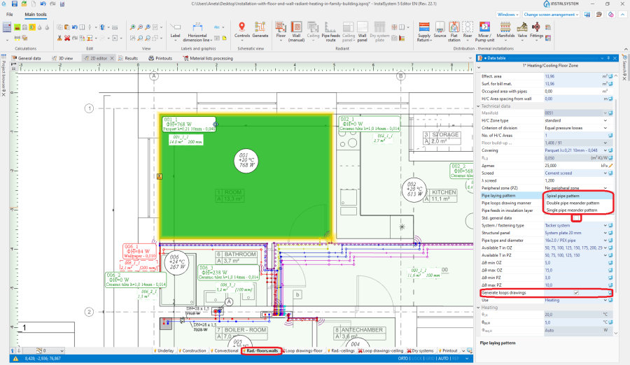
2. Pipe laying pattern
- The RHC loop tool available in Main tools, when working in the Loop drawings-floor/Loop drawings-ceiling editing range, enables manual drawing of loops. Use of this tool is recommended with the AUTO mode and GRID mode enabled (the grid has two levels - large and small dots).
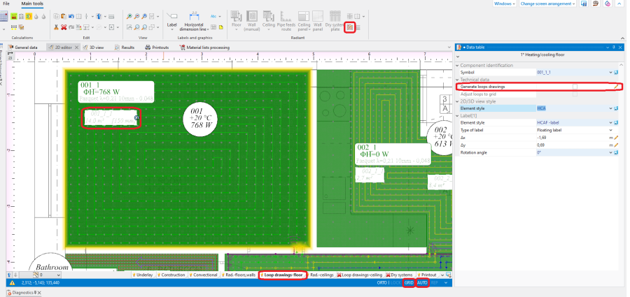
3.Loop drawings - Graphical editing


Example of use
Automatic generation of loop drawings
- Enable Generate loops drawings in General data window or for selected components.
- Calculate the project
 . Upon calculating the project, loop drawings will be generated automatically.
 - Change direction of loop arrangement (option).
After selecting Heating-cooling surface hotpoints of loop laying direction become available , and in the case of Single pipe meander pattern/Double pipe meander pattern a pointer is also available
  for indicating the side along which meandering is to be done. To display the effect of changing the loop laying direction and of indicating other side, the file must be recalculated.


- Verify how the Heating-cooling surface components are filled with RHC loop component, in particular check that there are no empty spaces. It is possible to fill such areas with pipes at a spacing smaller than the one calculated/specified for the zone. The functioning of this mechanism can be verified for:
- entire project - in the General data window on the Radiant systems - Additional options tab,

4. Manner of drawing a loop for the entire project - the Heating/Cooling Floor Zone component, after selecting it, in the Data table window, field Pipe loops drawing manner.

5. Manner of drawing a loop for the selected component Heating/Cooling Floor Zone
- entire project - in the General data window on the Radiant systems - Additional options tab,


Manual editing of loop drawings
- Disable generation of loop drawings for selected components Heating-cooling surface.
Attention! Clearing the Generate loops drawings option does not remove existing drawings of loops, it only freezes them in their current state and enables manual editing or deleting thereof. To completely remove loop drawings double left click the loop and select Delete selected components. - Enable the GRID mode which helps in correcting or manual drawing of loops. Large grid nodes are arranged at a distance calculated/specified for the given surface, small grid nodes are arranged at the minimum distance allowable for the selected pipe laying pattern. Colours of grid nodes are repeated for the current pipe spacing, which facilitates drawing with the use of that spacing. The grid can be arranged parallel to selected edge of component Heating/Cooling Floor Zone by positioning on that edge the blue hot-point
 . It becomes available when component Heating/Cooling Floor Zone is selected.
 - Correct/draw manually selected segments of loop.
- Contain the entire loop drawn within the Heating-cooling surface and finish drawing at its border.

Manual editing may also be necessary in some design situations, when the automatically generated loop is incorrect. The most common flaws include:
- start and end of loop drawing cross over,
- inconsistent pipe spacing in the loop,
- asymmetrical arrangement of the loop drawing in adjacent Heating-cooling surface components,
- incorrect drawings of pipe feed to loop connection points.
In each of these cases it is possible to manually fix the drawings as shown in the videos below.
Start and end of loop drawing cross over
Change the direction of drawing the loop or change the location of pipe feed connections.
Inconsistent pipe spacing in the loop
When the Heating-cooling surface is filled incorrectly (e.g. when there are different pipe spacings within one loop or when adjacent surfaces are filled asymmetrically), do the following:
- Mark the Adjust loops to grid in the Data table of the Heating-cooling surface
- Enable GRID
- If necessary, adjust the size of the Heating-cooling surface.
Incorrect drawings of pipe feed to loop connection points
Change the location of pipe feed connection points.
Incorrect generation of pipe spacing
Change of pipe spacing.
Manual editing of loop drawings in dry systems with guide plates
W przypadku podłogowych systemów suchych z ułożonymi w programie elementami katalogowymi Dry system plate, rolę siatki wykorzystywanej w celu kontroli poprawnego rozprowadzenia pętli pełnią charakterystyczne punkty płyt. For more information, see: Inserting plates in dry floor heating system.
W celu wygenerowania rysunków pętli należy w oknie General data włączyć ustawienia:
- Na zakładce Floor systems włączyć opcję Generate loops drawings oraz wybrać Single pipe meander pattern w polu Pipe laying pattern.
- (Opcjonalnie) Na zakładce Additional options włączyć opcję Take into account in calculations: drawing loop length. For more information, see: Jak uwzględnić rysunkową długość pętli w obliczeniach.
Po przeliczeniu projektu należy zweryfikować ułożenie pętli względem rówków elementów Dry system plate. W razie potrzeby wykonać ręczną edycję wygenerowanych pętli zgodnie z poniższymi wskazówkami:
- Zmienić bok wzdłuż którego będzie się odbywać meandrowanie oraz zmienić kierunek układania pętli. For more information, see: Automatyczne generowanie rysunków pętli.
- Wyłączyć Automatic division of heating zone i ręcznie skorygować przebieg krawędzi podziału.
- Wyłączyć Generate loops drawings w oknie Data table dla wybranych elementów Heating/cooling floor i ręcznie skorygować/uzupełnić rysunki pętli:
- Włączyć tryb pracy GRID w celu wyświetlenia punktów charakterystycznych w płytach systemu suchego.
- Poprawić położenie pętli (jej pojedynczych odcinków lub wielu odcinków grupowo zaznaczonych) względem punktów charakterystycznych oraz rowków płyt. Przy aktywnym trybie GRID i AUTO przesuwane odcinki pętli snapują się do punktów charakterystycznych płyt systemu suchego.
- W razie potrzeby ręcznie dorysować odcinki pętli korzystając z elementu RHC loop dostępnego na pasku Main tools w sekcji Radiant dla aktywnego zakresu Loop drawings-floor.
Uwaga! Aby zweryfikować efekt wprowadzonych zmian, konieczne jest ponowne przeliczenie pliku projektu.
Additional information
- RHC loop has its place in the Component appearance and descriptions configuration tree. In order to improve the legibility of loop printouts, the following settings can be checked in Coil configuration:
- Different circuit colours
- Pipefeeds use same colour as coil.


- Loop drawings are not mandatory and they do not have to be complete if the Take into account in calculations: drawing loop length option has not been selected.
- In the case of virtual connections, automatically generated loops originate from arbitrary points indicated by the program. After pipe feeds are drawn, the starting points of loops are automatically relocated. The loop drawings can also be automatically modified due to the routes of pipe feeds to other areas/rooms being taken into account.
- Pipe laying pattern can be changed for the entire project on the General data tab or for a single Heating/cooling floor.