Linear and point thermal bridges
Revision as of 10:00, 29 April 2025 by Klintsevicho (talk | contribs) (→Scenario III - method of accounting linear thermal bridges)
| Product | InstalSystem 5 |
| Type of article | FUNCTION AND TOOL |
| Source for translation | 2025-04-22 |
DESCRIPTION
This article describes methods of accounting linear and point thermal bridges in thermal calculations of partitions and building structures.
LOCATION IN THE PROGRAM
The selection of the is available in the window, tab.

EXAMPLE OF USE
Scenario I - method of accounting linear thermal bridges
- Editing the default data:
- In the window, , tab choose for the . Note: this method is available for the EN standards;
- (Optionally) for the . This causes the auto mode status to be set for all fields of the () column, available on the form / , with the following default values:
- = 0.05 - for the external partitions (, , , , ) and for thr partitions in contact with the ground (, );
- = 0.00 - for the internal partitions (, , , ).
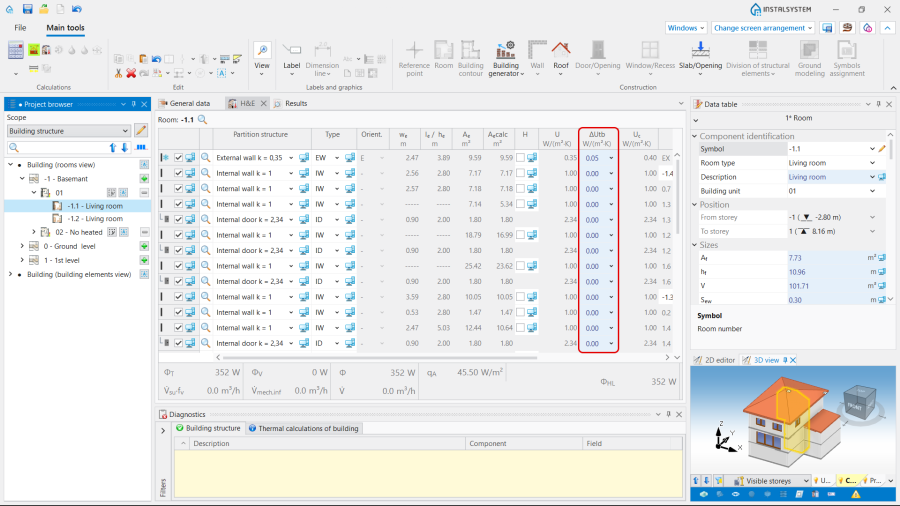
2. column with "auto mode" status.
- (Optionally) Introducing - available for the DIN standards.
- Editing the :
- Select the method of determine () in the form / :
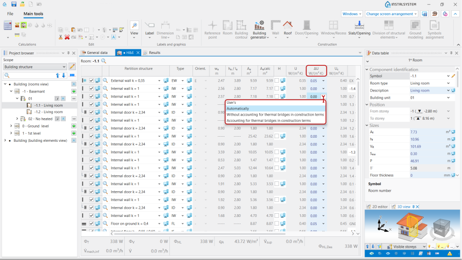
3. .
- User's - allows to set the value of the allowance by yourself;
- Automaticaly - initialises the default values according to the auto mode;
- - = 0.05 ;
- - = 0.1 .
- Select the method of determine () in the form / :


Scenario II - method of accounting linear thermal bridges
- Editing the default data:
- In the window, , tab choose for the . Note: this method is available for the EN standards.
- Editing the :
- Select the method of determine () in the form / , just like in Scenario I - Simplified method of accounting linear thermal bridges.
Scenario III - method of accounting linear thermal bridges
- Editing the default data:
- In the window, , tab choose for the . Note: this method is available for the EN standards.
- Definition of default types of the linear thermal bridges:
- After making the of linear thermal bridges will be available in the () scope. Open , , . Select the default definition for each type of linear thermal bridge from the offered visualized variants. Note: One definition per bridge type is available by default.
Once a linear bridge is defined, its description will be available in the working space and in the :- ,
- ,
- (from the visualized variants),
- , ().
- (Optionally) Copy an existing thermal bridge definition and modify its data, indicate as default;
- (Optionally) Create a new bridge definition, manually complete its data, select a bridge category from the list and indicate as default;
- (Optionally) Deletion of selected user bridge definitions.
- After making the of linear thermal bridges will be available in the () scope. Open , , . Select the default definition for each type of linear thermal bridge from the offered visualized variants. Note: One definition per bridge type is available by default.
- Perform , resulting in automatic detection of linear bridges and their inclusion in the ;
- Overview of automatically recognized linear thermal bridges and make manual edits, if necessary:
- Open , , . The tree presents the linear bridges within the rooms grouped by type in the related branches. All the bridges of a given type within a room can be selected using the function or by the . Multi-selection with CTRL/SHIFT is also possible;
- The identified bridges are presented in the 2D plan view and in the 3D view on a separate edit range "OZC (MC).
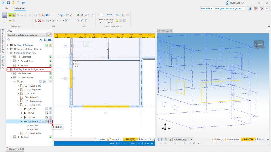
4. . - The selection of linear thermal bridges directly in the window or is also possible in the scope by clicking on its graphic representation.

- Editing the :
- Select the method of determine () in the form / , just like in Scenario I - Simplified method of accounting linear thermal bridges.