Import underlay files: Difference between revisions
Jump to navigation
Jump to search
| Line 33: | Line 33: | ||
===Import podkładu=== | ===Import podkładu=== | ||
# Select ''<IS_TS id=btImportujPodkladZPlikuDXF/>''. | # Select ''<IS_TS id=btImportujPodkladZPlikuDXF/>''. | ||
# | # Select the underlay file to be imported. | ||
# | # Indicate the position of the underlay in the ''<IS_TS id=lystrGraphicBackground/>'' editing scope. | ||
# | # Verify that the dimensions of the underlay are adequate.<br/>The size of the underlay can be changed in the component data table or using the ''<IS_TS id=strTabSkalowanieCaption/>'' tool, which requires drawing a line segment and specifying its real length. Additionally, in the case of a DWF/DXF file, a conversion factor between a CAD unit and a multiple or sub-multiple of a metre can be selected in the data table. | ||
# | # Verify the underlay save (storage) location option.<br/>The underlay may be stored in the project file *.ISPROJ, in which case the size of that file is increased (identical underlay files placed on multiple worksheets do not inflate the project file in proportion to the number of times the underlay is used), or it may remain in a separate (original) file to which the project will refer. The latter solution requires, when the project file is handed over to another person, that the underlay files are also turned over and the access paths to the files in the computer are specified. | ||
# | # Verify proper mutual alignment of underlays on the individual storeys. To obtain proper structure of a multi-storey building it is advisable to use a ''<IS_TS id=iNameReferencePoint/>''[[File:Reference-point.png|40 px|]], wherein one reference point is placed in each worksheet at a location having identical real coordinates X,Y.<br/>{{#ev:youtube|So_4l7ZUirY|900||||rel=0}} <br clear="all"/> | ||
==Additional information== | ==Additional information== | ||
Revision as of 00:51, 3 November 2016
| Product | InstalSystem 5 |
| Type of article | FUNCTIONALITY |
| Source for translation | IS 5.0 Beta 34 |
Description
The article describes the functionality of using design underlays (base drawings) by launching underlay import, selecting an external file to be imported, inserting the underlay in the project and appropriate scaling and positioning thereof.
Compatible underlay file formats:
- DWG
- BMP
- PNG
- JPG
- GIF
- DXF
Location in the program
- Icons of the components and functions related to importing an underlay are available in the 2D Editor window in the Main tools toolbar, section Underlay, when the Underlay editing scope is enabled.
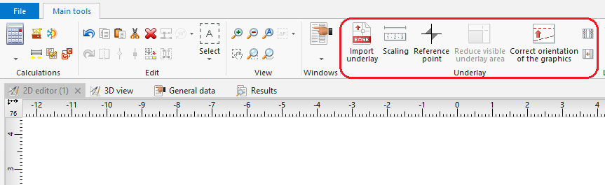
1. Import underlay

Example of use
Import podkładu
- Select Import underlay.
- Select the underlay file to be imported.
- Indicate the position of the underlay in the Underlay editing scope.
- Verify that the dimensions of the underlay are adequate.
The size of the underlay can be changed in the component data table or using the Scaling tool, which requires drawing a line segment and specifying its real length. Additionally, in the case of a DWF/DXF file, a conversion factor between a CAD unit and a multiple or sub-multiple of a metre can be selected in the data table. - Verify the underlay save (storage) location option.
The underlay may be stored in the project file *.ISPROJ, in which case the size of that file is increased (identical underlay files placed on multiple worksheets do not inflate the project file in proportion to the number of times the underlay is used), or it may remain in a separate (original) file to which the project will refer. The latter solution requires, when the project file is handed over to another person, that the underlay files are also turned over and the access paths to the files in the computer are specified. - Verify proper mutual alignment of underlays on the individual storeys. To obtain proper structure of a multi-storey building it is advisable to use a Reference point
 , wherein one reference point is placed in each worksheet at a location having identical real coordinates X,Y.
Additional information
- Szczególnie korzystna jest możliwość importu podkładu w formacie DWG, gdyż podczas późniejszej edycji konstrukcji będzie dostępna opcja przyciągania kursora do elementów zlokalizowanych na wskazanych warstwach podkładu (funkcja snapowania).
- Istnieje możliwości ograniczenia widocznego obszaru dla podkładów np. zawierających wiele rzutów pięter na jednym arkuszu. Operacja ograniczenia widocznego obszaru może zostać anulowana na każdym etapie tworzenia projektu.
- Jeżeli podkład podzielony jest na kilka części (np. w wyniku skanowania) można te części zaimportować osobno i połączyć w programie za pomocą funkcjonalności Combine base files.