Hydraulic control loop: Difference between revisions
Klintsevicho (talk | contribs) |
Klintsevicho (talk | contribs) No edit summary |
||
| Line 29: | Line 29: | ||
==Examples of use== | ==Examples of use== | ||
''<IS_TS id=iNameCOWezelRegulacyjny/>'' is a prefabricated block of grouped elements and is not graphically editable. May include a pump, balancing valves, control valves and overflow-relief valve. Allows the use of valves and fittings only from a list of items, suitable for use in a given location, in a configuration precisely defined by producers. | ''<IS_TS id=iNameCOWezelRegulacyjny/>'' is a prefabricated block of grouped elements and is not graphically editable. May include a pump, balancing valves, control valves and overflow-relief valve. Allows the use of valves and fittings only from a list of items, suitable for use in a given location, in a configuration precisely defined by producers. <br/>[[File:HCL toolbar.png |900 px|left|thumb|5. <IS_TS id=iNameCOWezelRegulacyjny/> visibility.]]<br clear="all"/> | ||
[[Category:InstalSystem 5]] | [[Category:InstalSystem 5]] | ||
[[Category:FUNCTION AND TOOL]] | [[Category:FUNCTION AND TOOL]] | ||
Revision as of 11:51, 30 January 2026
| Product | InstalSystem 5 |
| Type of article | FUNCTION AND TOOL |
| Source for translation | 2026-01-27 |
Description
Hydraulic control loop is the element used to hydraulically balance and regulate (qualitatively or quantitatively) the thermal efficiency of the end receiver (e.g., fan-coil or cooling beam). The article describes the ways of applying the element in the program.
Location in program
Hydraulic control loop is presented in the program as a separate module, the availability of which is visible in the InstalSystem 5.5 Manager / Help tab / list of Modules available in current licence configuration:

To use the Hydraulic control loop element, the corresponding catalogues should be selected and added to the project in the General data window / Catalogues tab. For more information, see: Selecting catalogues for the project.

The element can be placed on the drawing when Convectional, Rad.-floors,walls or Rad.-ceilings editing scope is active:
- clicking the icon Hydraulic control loop in the Distribution - thermal installations tab in the Main tools menu:
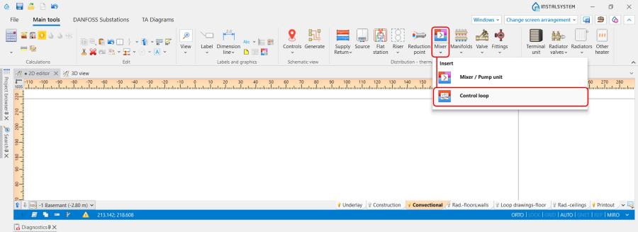
3. Hydraulic control loop icon. - clicking the icon with schemes presented by the particular producers:
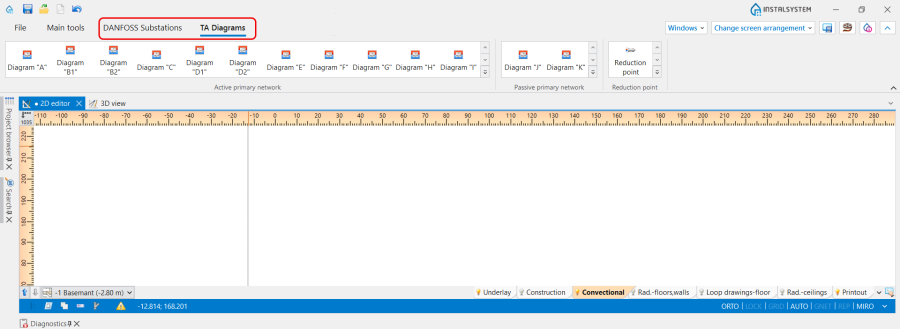
4. Hydraulic control loop schemes.

Examples of use
Hydraulic control loop is a prefabricated block of grouped elements and is not graphically editable. May include a pump, balancing valves, control valves and overflow-relief valve. Allows the use of valves and fittings only from a list of items, suitable for use in a given location, in a configuration precisely defined by producers.
