Automatically generate schematic views: Difference between revisions
| Line 43: | Line 43: | ||
* ''<IS_TS id=iNameOP2Rozdz/>'' | * ''<IS_TS id=iNameOP2Rozdz/>'' | ||
* ''<IS_TS id=StacjaMieszkaniowa/>''<br/>[[File:Schematic-view-Starting-Point-2.png|900 px|left|thumb|2. ''<IS_TS id=rpCreateSchematicStartPointT/>'']]<br clear="all"/> | * ''<IS_TS id=StacjaMieszkaniowa/>''<br/>[[File:Schematic-view-Starting-Point-2.png|900 px|left|thumb|2. ''<IS_TS id=rpCreateSchematicStartPointT/>'']]<br clear="all"/> | ||
#''<IS_TS id=TypDzialkiWiodacej/>''<br/> | #''<IS_TS id=TypDzialkiWiodacej/>''<br/>Indication of the pipe-run which has a priority when generating a schematic view. This is important when generating an asymmetrical installation (supply and return pipe-runs arranged along different routes). All junctions (tees, crosspieces) are also marked on leading pipe-runs.<br/>[[File:Schematic-view-Tee2.png|900 px|left|thumb|3. Junction(tee)]]<br clear="all"/>can be reduced: | ||
#* ''<IS_TS id=ElementyPrezentowaneNaRozwZrodloDoPionu/>'' - generates the schematic view from the indicated point to stacks, excluding the stacks | |||
#* ''<IS_TS id=ElementyPrezentowaneNaRozwZrodloDoPionu/>'' - | #* ''<IS_TS id=ElementyPrezentowaneNaRozwPiony/>'' - generates the schematic view from the indicated point to stacks, including the stacks | ||
#* ''<IS_TS id=ElementyPrezentowaneNaRozwPiony/>'' - | #* ''<IS_TS id=ElementyPrezentowaneNaRozwZaPionami/>'' - generates the schematic view from the indicated point beyond the stacks to terminal units.If an installation includes stations, the schematic view is terminated at the station, if the installation includes manifolds, the schematic view is tgerminated at the manifold. | ||
#* ''<IS_TS id=ElementyPrezentowaneNaRozwZaPionami/>'' - | #* ''<IS_TS id=ElementyPrezentowaneNaRozwZaSM/>'' - generates the schematic view from the indicated point to the station including the installation beyond the station (checkbox ''<IS_TS id=ElementyPrezentowaneNaRozwZaPionami/>'' must be checked) | ||
#* ''<IS_TS id=ElementyPrezentowaneNaRozwZaSM/>'' - | #* ''<IS_TS id=ElementyPrezentowaneNaRozwZaRozdz/>'' - generates the schematic view beyond the manifolds (checkbox ''<IS_TS id=ElementyPrezentowaneNaRozwZaPionami/>'' must be checked)<br/>{{#ev:youtube|M5EEbhoIO5U|900||||rel=0}} <br clear="all"/> | ||
#* ''<IS_TS id=ElementyPrezentowaneNaRozwZaRozdz/>'' - | # Control over automatic labelling.<br/>[[File:Schematic-view-Labels-2.png|900 px|left|thumb|10. Schematic view - labels control]]<br clear="all"/> | ||
# | |||
#''<IS_TS id=PozornePrzesuniecie/>''<br/>Pozwala na prezentację na rozwinięciu działek prowadzonych na tej samej rzędnej. Wartość ta nie ma wpływu na rzędną działki w modelu. | #''<IS_TS id=PozornePrzesuniecie/>''<br/>Pozwala na prezentację na rozwinięciu działek prowadzonych na tej samej rzędnej. Wartość ta nie ma wpływu na rzędną działki w modelu. | ||
#* | #* Positive value - this value is added to the elevation of the supply pipe-run in the schematic view. | ||
#* | #* Negative value - this value is subtracted from the elevation of the supply pipe-run in the schematic view.<br/>[[File:Schematic-view-Phantom-3.png|900 px|left|thumb|4. ''<IS_TS id=PozornePrzesuniecie/>'']]<br/>[[File:Schematic-view-Phantom-4.png|900 px|left|thumb|5. ''<IS_TS id=PozornePrzesuniecie/>'' - supply and retirn]]<br clear="all"/> | ||
#''<IS_TS id=ShowRoomsCaption/>''<br/>Oznaczane są obszary pomieszczeń i ich etykiety.<br/>[[File:Schematic-view-Show-Room-Extent-4.png|900 px|left|thumb|6. ''<IS_TS id=ShowRoomsCaption/>'']]<br/>[[File:Schematic-view-Show-Room-Extent-3.png|900 px|left|thumb|7. ''<IS_TS id=ShowRoomsCaption/>'' - zaznaczone pomieszczenie na rozwinięciu]]<br clear="all"/> | #''<IS_TS id=ShowRoomsCaption/>''<br/>Oznaczane są obszary pomieszczeń i ich etykiety.<br/>[[File:Schematic-view-Show-Room-Extent-4.png|900 px|left|thumb|6. ''<IS_TS id=ShowRoomsCaption/>'']]<br/>[[File:Schematic-view-Show-Room-Extent-3.png|900 px|left|thumb|7. ''<IS_TS id=ShowRoomsCaption/>'' - zaznaczone pomieszczenie na rozwinięciu]]<br clear="all"/> | ||
#''<IS_TS id=GenerateSchematicWorksheet/>''<br/> | #''<IS_TS id=GenerateSchematicWorksheet/>''<br/>Unchecking this option disables the generation of the schematic view during subsequent generations, e.g. new settings for the automatic schematic view control functions will not be taken into account. However, disabling this option does not affect installation components. The installation components are refreshed automatically, i.e. the number of installation components in the model always corresponds to the number of installation components in the schematic view. If this option is disabled, a padlock icon is shown in the sheet selection list [[File:Schematic-view-Sheet-iko-2.png|36 px|]].<br/>[[File:Schematic-view-Generate-schematic-2.png|900 px|left|thumb|8. '<IS_TS id=GenerateSchematicWorksheet/>'']]<br clear="all"/> | ||
====''<IS_TS id=SchematicGuide/>''==== | ====''<IS_TS id=SchematicGuide/>''==== | ||
Revision as of 20:01, 20 January 2020
| Product | InstalSystem 5 |
| Type of article | FUNCTIONS AND TOOLS |
| Source for translation | REVISION Rev. 17.1 |
Description
This article describes the method of creating automatic schematic views of installations based on an installation model of Application: Heating systems or Application: Cooling systems type with an option to manually edit these views, insert fittings and regenerate the view at any time.
Schematic views of installations are generated in the 2D editor using Starting point (thermal installations) components.
This functionality is currently under development and was included in the BETA version.
Location in the program
Icons of components and of functions for controlling the automatical generation of schematic views are available in the 2D editor window on the Main tools bar in the Schematic view section within the Convectional, Rad.-floors,walls, Rad.-ceilings editing scopes.

The generated Sheet type: Schematic view components are at the bottom of the sheet list.

Examples of use
Check connections
Checking the correctness of connections using the Check connections operation or by pressing Shift+F2 is necessary for the proper generation of the schematic view. The project file can include messages on error relevance, but these messages cannot relate to connection errors.
Presentation of the basic components and functions for controlling automatic generation of schematic views
Starting point (thermal installations)
This is the starting point in the installation from which the schematic view is generated. It has to be assigned a unique symbol. Many Starting point (thermal installations) components can be inserted, and each of them generates a separate Sheet type: Schematic view ![]()
The Starting point (thermal installations) can be placed on:
- Source
- Riser
- Pipe-runs pair
- Double manifold
- Flat station

2. Starting point (thermal installations)

- Leading pipe-run
Indication of the pipe-run which has a priority when generating a schematic view. This is important when generating an asymmetrical installation (supply and return pipe-runs arranged along different routes). All junctions (tees, crosspieces) are also marked on leading pipe-runs.
3. Junction(tee)
can be reduced:- Installation between source and risers - generates the schematic view from the indicated point to stacks, excluding the stacks
- Risers - generates the schematic view from the indicated point to stacks, including the stacks
- Installation behind risers - generates the schematic view from the indicated point beyond the stacks to terminal units.If an installation includes stations, the schematic view is terminated at the station, if the installation includes manifolds, the schematic view is tgerminated at the manifold.
- Installation behind flat stations - generates the schematic view from the indicated point to the station including the installation beyond the station (checkbox Installation behind risers must be checked)
- Installation behind manifold - generates the schematic view beyond the manifolds (checkbox Installation behind risers must be checked)
- Control over automatic labelling.

10. Schematic view - labels control - Apparent shift
Pozwala na prezentację na rozwinięciu działek prowadzonych na tej samej rzędnej. Wartość ta nie ma wpływu na rzędną działki w modelu.- Positive value - this value is added to the elevation of the supply pipe-run in the schematic view.
- Negative value - this value is subtracted from the elevation of the supply pipe-run in the schematic view.

4. Apparent shift 
5. Apparent shift - supply and retirn
- Show room extent
Oznaczane są obszary pomieszczeń i ich etykiety.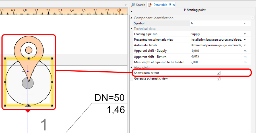
6. Show room extent 
7. Show room extent - zaznaczone pomieszczenie na rozwinięciu - Generate schematic views
Unchecking this option disables the generation of the schematic view during subsequent generations, e.g. new settings for the automatic schematic view control functions will not be taken into account. However, disabling this option does not affect installation components. The installation components are refreshed automatically, i.e. the number of installation components in the model always corresponds to the number of installation components in the schematic view. If this option is disabled, a padlock icon is shown in the sheet selection list .
.
8. 'Generate schematic views


Control point
Pozwala na kontrolę kierunku generacji poszczególnych gałęzi na rozwinięciu oraz na modyfikację przebiegu trasy wiodącej. Musi być wstawiony na działkę wiodącą. Punkt sterujący zmienia przebieg rozwinięcia począwszy od węzła, za którym został wstawiony. Elementów Control point może być wstawionych wiele i mogą być wstawione na Sheet type: Schematic view lub Sheet type: Plan view.

- Direction.
Pozwala określić np. czy fragment instalacji (np.: Riser) ma być traktowany jako ułożony po prawej lub lewej stronie od elementu Source. Analogicznie można określić czy fragment instalacji jest po prawej lub lewej stronie od elementu Riser. Na filmie zaprezentowano przeniesienie na rozwinięciu dwóch pionów na lewo od źródła.
- Disconnect on schematic view.
Pozwala na korektę przebiegu trasy wiodącej rozwinięcia. Na filmie zaprezentowano zmianę trasy wiodącej w taki sposób, aby trasa krytyczna instalacji była zaprezentowana jako pierwsza.
Endpoint
Program nie generuje rozwinięcia instalacji znajdującej się za elementem Endpoint. Ta część instalacji zastępowana jest elementem Fragment of installation. Element Endpoint musi mieć nadany unikalny symbol.
Na filmie zaprezentowano eliminację pionu z rozwinięcia.
Fragmenty instalacji nie podlegające automatycznemu generowaniu rozwinięcia
- Instalacje z panelami sufitowymi.
- Instalacje z panelami ściennymi.
Takie fragmenty są automatycznie kończone elementem Fragment of installation.
Edycja ręczna i konfiguracja
- Wstawianie elementów niezależnych.
Na Sheet type: Schematic view można wstawiać:- dodatkowe etykiety (np.: etykiety działek). Można zmieniać również położenie wstawionych etykiet i program zachowuje ich położenie po regeneracji rozwinięcia,
- zawory,
- armaturę wstawianą na działki,
- armaturę grzejnikową.
Dodatkowe informacje
- Plik projektu z programu InstalSystem 4 zawierający Sheet type: Schematic view wczytany do InstalSystem 5.
Taki arkusz nie jest konwertowany na Sheet type: Schematic view z programu InstalSystem 5 i jest on usuwany podczas wczytywania, o czym program informuje odpowiednim komunikatem diagnostyki.