Appending drawings with radiant system loops: Difference between revisions
No edit summary Tag: Manual revert |
|||
| (100 intermediate revisions by 12 users not shown) | |||
| Line 1: | Line 1: | ||
<IS_HELP id="HS101"/> | |||
<!-- case 186552 - aktualizacja--> | |||
<!-- case 282393 - aktualizacja--> | |||
{{Article table | {{Article table | ||
|commercial_product1=InstalSystem 5 | |commercial_product1=InstalSystem 5 | ||
| Line 5: | Line 8: | ||
|p4 =<!--gdy jest kolejny produkt handlowy, zamienić na->"produkt_handlowy3="--> | |p4 =<!--gdy jest kolejny produkt handlowy, zamienić na->"produkt_handlowy3="--> | ||
|category1 =InstalSystem 5#Funkctionalities | |category1 =InstalSystem 5#Funkctionalities | ||
|category_name1 = | |category_name1 =FUNCTION AND TOOL | ||
|c2 =<!--Jest kategoria -> zamienić na: "category2=" i uzupełnić link do sekcji kategorii na stronie głównej produktu--> | |c2 =<!--Jest kategoria -> zamienić na: "category2=" i uzupełnić link do sekcji kategorii na stronie głównej produktu--> | ||
|category_name2 =<!--podać nazwę kategorii--> | |category_name2 =<!--podać nazwę kategorii--> | ||
|c3 =<!--Jest kategoria -> zamienić na: "category3=" i uzupełnić link do sekcji kategorii na stronie głównej produktu--> | |c3 =<!--Jest kategoria -> zamienić na: "category3=" i uzupełnić link do sekcji kategorii na stronie głównej produktu--> | ||
|category_name3 =<!--podać nazwę kategorii "ZASTOSOWANIE"/"FUNKCJONALNOŚĆ"/...--> | |category_name3 =<!--podać nazwę kategorii "ZASTOSOWANIE"/"FUNKCJONALNOŚĆ"/...--> | ||
|version1 = | |version1 =2022-08-30 | ||
|v2 =<!--Jest wersja -> zamienić na: "version2=" i uzupełnić link do sekcji RN danego produktu--> | |v2 =<!--Jest wersja -> zamienić na: "version2=" i uzupełnić link do sekcji RN danego produktu--> | ||
|v3 =<!--Jest wersja -> zamienić na: "version2=" i uzupełnić link do sekcji RN danego produktu--> | |v3 =<!--Jest wersja -> zamienić na: "version2=" i uzupełnić link do sekcji RN danego produktu--> | ||
|v4 =<!--Jest wersja -> zamienić na: "version2=" i uzupełnić link do sekcji RN danego produktu--> | |v4 =<!--Jest wersja -> zamienić na: "version2=" i uzupełnić link do sekcji RN danego produktu--> | ||
}} | }} | ||
== | ==Description== | ||
'' | The ''<IS_TS id=strPGCh/>'' component (floors and ceilings) can be appended with drawings of loops. Drawings generated automatically by the program are refreshed each time the project is recalculated. It is possible to modify or append them and loops can be drawn manually. Manual editing is recommended at the final stage of design. | ||
==Videos related to the article== | |||
<br/> {{#ev:youtube|y3O2KyYPLpg|450||||rel=0}} <br clear="all"/> | |||
== | ==Location in the program== | ||
*''<IS_TS id=rsDanogi/>'' - | *''<IS_TS id=rsDanogi/>'' - automatic generation of loops can be enabled for all components by selecting the ''<IS_TS id=GenerujRysunkiPetli/>'' checkbox.<br/>[[File:Generate_loops_drawings.png|900 px|left|thumb|1. <IS_TS id=GenerujRysunkiPetli/>]]<br clear="all"/> | ||
*''<IS_TS id=DataEditorTable/>'' for component ''<IS_TS id=iNameOPStrefaPodlogGrzejnych/>'', when working in the ''<IS_TS id=ScopeInstalacjePodlogoweIScienneShort/>''/''<IS_TS id=ScopeInstalacjeSufitoweShort/>'' editing range, enables: | *''<IS_TS id=DataEditorTable/>'' for component ''<IS_TS id=iNameOPStrefaPodlogGrzejnych/>'', when working in the ''<IS_TS id=ScopeInstalacjePodlogoweIScienneShort/>''/''<IS_TS id=ScopeInstalacjeSufitoweShort/>'' editing range, enables: | ||
**automatic generation of loops by selecting the ''<IS_TS id=GenerujRysunkiPetli/>'' checkbox; loop generation can be disabled here for a selected component when this checkbox is selected in ''<IS_TS id=rsDanogi/>'', | **automatic generation of loops by selecting the ''<IS_TS id=GenerujRysunkiPetli/>'' checkbox; loop generation can be disabled here for a selected component when this checkbox is selected in ''<IS_TS id=rsDanogi/>'', | ||
**selection of pipe laying pattern.<br/>[[File:Suf-loops-dem-zone.png| | **selection of pipe laying pattern.<br/>[[File:Suf-loops-dem-zone.png|900 px|left|thumb|2. Pipe laying pattern]]<br clear="all"/> | ||
*The ''<IS_TS id=WezownicaCaption/>'' tool available in ''<IS_TS id=NarzedziaGlowne/>'', when working in the ''<IS_TS id=RysPetliPodlogoweCaption/>''/''<IS_TS id=RysPetliSufitoweCaption/>'' editing range, enables manual drawing of loops. Use of this tool is recommended with the ''<IS_TS id=strGRIDModeName/>'' mode enabled.<br/>[[File:Suf-loops-floor- | *The ''<IS_TS id=WezownicaCaption/>'' tool available in ''<IS_TS id=NarzedziaGlowne/>'', when working in the ''<IS_TS id=RysPetliPodlogoweCaption/>''/''<IS_TS id=RysPetliSufitoweCaption/>'' editing range, enables manual drawing of loops. Use of this tool is recommended with the ''<IS_TS id=strAUTOModeName/>'' mode and ''<IS_TS id=strGRIDModeName/>'' mode enabled (the grid has two levels - large and small dots).<br/>[[File:Suf-loops-floor-screen_mod.png|900 px|left|thumb|3.Loop drawings - Graphical editing]]<br clear="all"/> | ||
==Example of use== | ==Example of use== | ||
===Automatic generation of loop drawings=== | ===Automatic generation of loop drawings=== | ||
# Enable | # Enable ''<IS_TS id=GenerujRysunkiPetli/>'' in ''<IS_TS id=rsDanogi/>'' window or for selected components. | ||
# Calculate the project [[File:Loops-calculation.png|20 px]]. Upon calculating the project, loop drawings will be generated automatically.<br clear="all"/> | |||
# Change direction of loop arrangement (option).<br/>After selecting ''<IS_TS id=strPGCh/>'' hotpoints of loop laying direction become available [[File:Direction.png|20 px|]], and in the case of ''<IS_TS id=rsWariantUlozeniaPGPojedynczyMeander/>''/''<IS_TS id=rsWariantUlozeniaPGPodwojnyMeander/>'' a pointer is also available [[File:Side.png|20 px|]] for indicating the side along which meandering is to be done. To display the effect of changing the loop laying direction and of indicating other side, the file must be recalculated. | |||
# | {{#ev:youtube|9SCDgdIlNLY|900||||rel=0}}</br> | ||
# | # Verify how the ''<IS_TS id=strPGCh/>'' components are filled with ''<IS_TS id=WezownicaCaption/>'' component, in particular check that there are no empty spaces. It is possible to fill such areas with pipes at a spacing smaller than the one calculated/specified for the zone. The functioning of this mechanism can be verified for: | ||
#* entire project - in the ''<IS_TS id=rsDanogi/>'' window on the ''<IS_TS id=SystemyPlaszczyznowe/>'' - ''<IS_TS id=sOpcjeObliczen/>'' tab, [[File:Pipe loopps drawing manner ih Genera data.png|900 px|center|thumb|4. Manner of drawing a loop for the entire project]]<br clear="all"/> | |||
{{#ev:youtube| | #* the ''<IS_TS id=iNameOPStrefaPodlogGrzejnych/>'' component, after selecting it, in the ''<IS_TS id=DataEditorTable/>'' window, field ''<IS_TS id=SposobRysowaniaPetli/>''. <br/> [[File:Pipe_loops_drawin_manner_in_Data_table.png|900 px|center|thumb|5. Manner of drawing a loop for the selected component ''<IS_TS id=iNameOPStrefaPodlogGrzejnych/>'']]<br clear="all"/> | ||
{{#ev:youtube|WXzOUy51648|900||||rel=0}}<br clear="all"/> | |||
===Manual editing of loop drawings=== | ===Manual editing of loop drawings=== | ||
# Disable generation of loop drawings for selected components ''<IS_TS id=strPGCh/>''.<br/>''Attention!'' Clearing the ''<IS_TS id=GenerujRysunkiPetli/>'' option does not remove existing drawings of loops, it only freezes them in their current state and enables manual editing or deleting thereof. | # Disable generation of loop drawings for selected components ''<IS_TS id=strPGCh/>''.<br/>'''Attention!''' Clearing the ''<IS_TS id=GenerujRysunkiPetli/>'' option does not remove existing drawings of loops, it only freezes them in their current state and enables manual editing or deleting thereof. To completely remove loop drawings double left click the loop and select Delete selected components. | ||
# Enable the ''<IS_TS id=strGRIDModeName/>'' mode which helps in correcting or manual drawing of loops. | # Enable the ''<IS_TS id=strGRIDModeName/>'' mode which helps in correcting or manual drawing of loops. Large grid nodes are arranged at a distance calculated/specified for the given surface, small grid nodes are arranged at the minimum distance allowable for the selected pipe laying pattern. Colours of grid nodes are repeated for the current pipe spacing, which facilitates drawing with the use of that spacing. The grid can be arranged parallel to selected edge of component ''<IS_TS id=iNameOPStrefaPodlogGrzejnych/>'' by positioning on that edge the blue hot-point [[File:Hot-point-obrot.png|20 px]]. It becomes available when component ''<IS_TS id=iNameOPStrefaPodlogGrzejnych/>'' is selected. | ||
# Correct/draw manually selected segments of loop. | # Correct/draw manually selected segments of loop. | ||
{{#ev:youtube| | # Contain the entire loop drawn within the ''<IS_TS id=strPGCh/>'' and finish drawing at its border.<br/>{{#ev:youtube|DnJ8RWVPIyk|900||||rel=0}}<br clear="all"/> | ||
<!--case 165036="--> | |||
Manual editing may also be necessary in some design situations, when the automatically generated loop is incorrect. The most common flaws include: | |||
* start and end of loop drawing cross over, | |||
* inconsistent pipe spacing in the loop, | |||
* asymmetrical arrangement of the loop drawing in adjacent ''<IS_TS id=strPGCh/>'' components, | |||
* incorrect drawings of pipe feed to loop connection points. | |||
In each of these cases it is possible to manually fix the drawings as shown in the videos below.</br> | |||
</br> | |||
====Start and end of loop drawing cross over==== | |||
Change the direction of drawing the loop or change the location of pipe feed connections. | |||
{{#ev:youtube|q2n3HBBYnLQ|900||||rel=0}} <br clear="all"/> | |||
====Inconsistent pipe spacing in the loop==== | |||
When the ''<IS_TS id=strPGCh/>'' is filled incorrectly (e.g. when there are different pipe spacings within one loop or when adjacent surfaces are filled asymmetrically), do the following: | |||
*Mark the ''<IS_TS id=RysPetliOparteOSiatkeCaption/>'' in the ''<IS_TS id=DataEditorTable/>'' of the ''<IS_TS id=strPGCh/>'' | |||
*Enable ''<IS_TS id=strGRIDModeName/>'' | |||
*If necessary, adjust the size of the ''<IS_TS id=strPGCh/>''. | |||
{{#ev:youtube|9fo-FK2STsg|900||||rel=0}} <br clear="all"/> | |||
====Incorrect drawings of pipe feed to loop connection points==== | |||
Change the location of pipe feed connection points. | |||
{{#ev:youtube|pGoLLnKMZ4M|900||||rel=0}} <br clear="all"/> | |||
====Incorrect generation of pipe spacing==== | |||
Change of pipe spacing. | |||
{{#ev:youtube|oNXwMLft4YU|900||||rel=0}}<br/> | |||
===Manual editing of loop drawings in dry systems with guide plates=== | |||
<!--case 165036="--> | |||
In the case of dry floor systems with arranged ''<IS_TS id=KlocekDrySysName/>'' components from a catalogue, the role of the grid used for controlling proper routing of the loop is taken on by characteristic points of the plates. {{Info}} [[Inserting plates in dry floor heating system]].</br></br>In order to generate loop drawings the following settings must be made in the ''<IS_TS id=rsDanogi/>'' window: | |||
* On the ''<IS_TS id=DaneInstalacjiPodlogowych/>'' tab enable the ''<IS_TS id=GenerujRysunkiPetli/>'' option and select ''<IS_TS id=strPojedynczyMeander/>'' in the ''<IS_TS id=strWariantUlozenia/>'' field. | |||
* (Optionally) On the ''<IS_TS id=sOpcjeObliczen/>'' tab enable the ''<IS_TS id=UwzglednianieDlugosciPetliGroup/>'' ''<IS_TS id=UwzgledniajRysDlugPetli/>'' option. {{Info}} [[How to include the drawing loop length in the calculations?]]. | |||
After the project is calculated the routing of the pipes in relation to the grooves in the ''<IS_TS id=KlocekDrySysName/>'' components should be verified. If necessary, edit manually the generated loops following these guidelines: | |||
* Change the side along which meandering is to be effected and change the direction of loop arrangement. {{Info}} [[Appending drawings with radiant system loops#Automatic generation of loop drawings|Automatic generation of loop drawings]]. | |||
* Disable ''<IS_TS id=ModeAutoDivideHeatingZone/>'' and manually change the arrangement of division lines. | |||
* Disable ''<IS_TS id=GenerujRysunkiPetli/>'' in the ''<IS_TS id=DataEditorTable/>'' window for selected ''<IS_TS id=iNameOPGrzejnik/>'' components and manually change/append the loop drawings: | |||
** Enable the ''<IS_TS id=strGRIDModeName/>'' mode to display the characteristic points of dry system plates. | |||
** Adjust the position of the loop (of its individual segments or many segments marked as a group) in relation to the characteristic points and grooves in plates. When the ''<IS_TS id=strGRIDModeName/>'' and ''<IS_TS id=strAUTOModeName/>'' modes are enabled, the moved loop segments will snap to the characteristic points of dry system plates. | |||
** If necessary, manually draw loop segments using the ''<IS_TS id=WezownicaCaption/>'' component from the ''<IS_TS id=NarzedziaGlowne/>'' bar in section ''<IS_TS id=NazwaZakladkiOP/>'' for the enabled ''<IS_TS id=RysPetliPodlogoweCaption/>'' scope.<br/>{{#ev:youtube|rBMhxPUQpGY|900||||rel=0}} | |||
'''Attention!''' In order to verify the effects of the changes made it is necessary to recalculate the project file. | |||
==Additional information== | ==Additional information== | ||
* ''' | * ''<IS_TS id=WezownicaCaption/>'' has its place in the ''<IS_TS id=ConfigurationElementsAppereance/>'' tree. In order to improve the legibility of loop printouts, the following settings can be checked in ''<IS_TS id=KonfiguracjaWezownicy/>'': | ||
**''<IS_TS id=RozneKoloryPetli/>'' | |||
**''<IS_TS id=PrzylaczaMajaKolorWezownicy />''. | |||
[[File:RHCloop_style.png|900 px|center|thumb|6. <IS_TS id=ConfigurationElementsAppereance/> - <IS_TS id=WezownicaCaption/>]]<br clear="all"/> | |||
[[File: | [[File:RHCloop_colour.png|900 px|center|thumb|7. <IS_TS id=RozneKoloryPetli/>]]<br clear="all"/> | ||
[[File: | * Loop drawings are not mandatory and they do not have to be complete if the ''<IS_TS id=UwzglednianieDlugosciPetliGroup/>'' ''<IS_TS id=UwzgledniajRysDlugPetli/>'' option has not been selected. | ||
* ''' | * In the case of virtual connections, automatically generated loops originate from arbitrary points indicated by the program. After pipe feeds are drawn, the starting points of loops are automatically relocated. The loop drawings can also be automatically modified due to the routes of pipe feeds to other areas/rooms being taken into account.<br> | ||
* ''<IS_TS id=strWariantUlozenia/>'' can be changed for the entire project on the ''<IS_TS id=rsDanogi/>'' tab or for a single ''<IS_TS id=iNameOPGrzejnik/>''. | |||
{|class="wikitable" style="width: 800px; margin: 0 auto;" | |||
!If you have any comments on this article, please send us a short message at ''info@instalsoft.com''. | |||
|} | |||
[[Category:InstalSystem 5]] | [[Category:InstalSystem 5]] | ||
[[Category: | [[Category:FUNCTION AND TOOL]] | ||
<!-- Do not write text below this tag --> | |||
<br class="iwlinks"/>[[pl:Uzupełnienie rysunków o pętle instalacji płaszczyznowej|Uzupełnienie rysunków o pętle instalacji płaszczyznowej]][[it:Completamento dei disegni con serpentine dei sistemi radianti|Completamento dei disegni con serpentine dei sistemi radianti]][[zh-cn:添加辐射系统盘管图|添加辐射系统盘管图]][[bg:Добавяне на чертежи с лъчисти системни пръстени|Добавяне на чертежи с лъчисти системни пръстени]][[lt:Piešinių papildymas spindulinės sistemos kilpomis|Piešinių papildymas spindulinės sistemos kilpomis]] | |||
Latest revision as of 23:01, 12 June 2026
| Product | InstalSystem 5 |
| Type of article | FUNCTION AND TOOL |
| Source for translation | 2022-08-30 |
Description
The component (floors and ceilings) can be appended with drawings of loops. Drawings generated automatically by the program are refreshed each time the project is recalculated. It is possible to modify or append them and loops can be drawn manually. Manual editing is recommended at the final stage of design.
Location in the program
- - automatic generation of loops can be enabled for all components by selecting the checkbox.
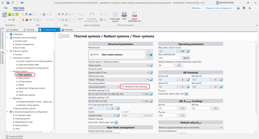
1. - for component , when working in the / editing range, enables:
- automatic generation of loops by selecting the checkbox; loop generation can be disabled here for a selected component when this checkbox is selected in ,
- selection of pipe laying pattern.
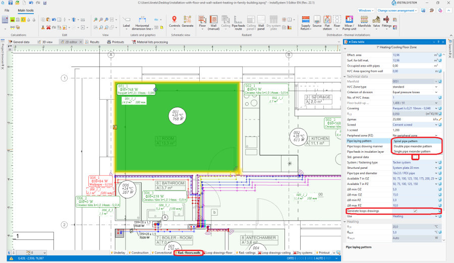
2. Pipe laying pattern
- The tool available in , when working in the / editing range, enables manual drawing of loops. Use of this tool is recommended with the mode and mode enabled (the grid has two levels - large and small dots).
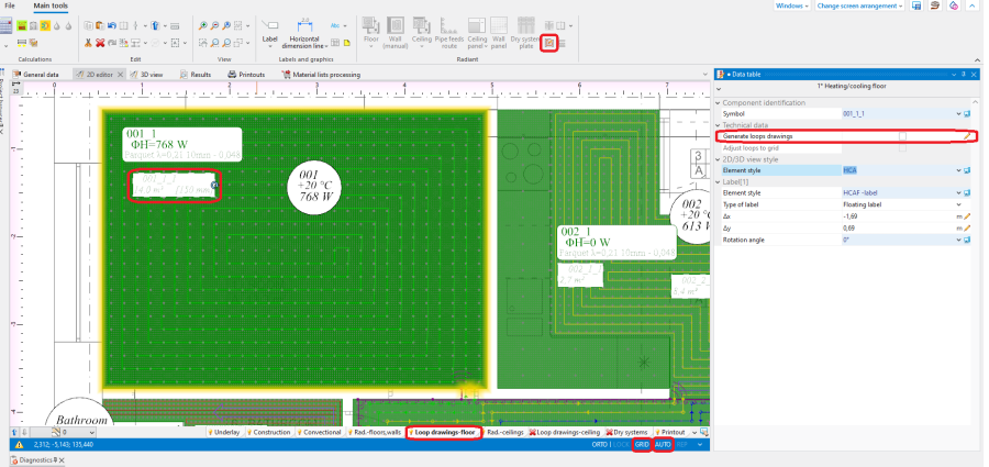
3.Loop drawings - Graphical editing


Example of use
Automatic generation of loop drawings
- Enable in window or for selected components.
- Calculate the project
 . Upon calculating the project, loop drawings will be generated automatically.
 - Change direction of loop arrangement (option).
After selecting hotpoints of loop laying direction become available , and in the case of / a pointer is also available
  for indicating the side along which meandering is to be done. To display the effect of changing the loop laying direction and of indicating other side, the file must be recalculated.


- Verify how the components are filled with component, in particular check that there are no empty spaces. It is possible to fill such areas with pipes at a spacing smaller than the one calculated/specified for the zone. The functioning of this mechanism can be verified for:
- entire project - in the window on the - tab,

4. Manner of drawing a loop for the entire project - the component, after selecting it, in the window, field .

5. Manner of drawing a loop for the selected component
- entire project - in the window on the - tab,


Manual editing of loop drawings
- Disable generation of loop drawings for selected components .
Attention! Clearing the option does not remove existing drawings of loops, it only freezes them in their current state and enables manual editing or deleting thereof. To completely remove loop drawings double left click the loop and select Delete selected components. - Enable the mode which helps in correcting or manual drawing of loops. Large grid nodes are arranged at a distance calculated/specified for the given surface, small grid nodes are arranged at the minimum distance allowable for the selected pipe laying pattern. Colours of grid nodes are repeated for the current pipe spacing, which facilitates drawing with the use of that spacing. The grid can be arranged parallel to selected edge of component by positioning on that edge the blue hot-point
 . It becomes available when component is selected.
 - Correct/draw manually selected segments of loop.
- Contain the entire loop drawn within the and finish drawing at its border.

Manual editing may also be necessary in some design situations, when the automatically generated loop is incorrect. The most common flaws include:
- start and end of loop drawing cross over,
- inconsistent pipe spacing in the loop,
- asymmetrical arrangement of the loop drawing in adjacent components,
- incorrect drawings of pipe feed to loop connection points.
In each of these cases it is possible to manually fix the drawings as shown in the videos below.
Start and end of loop drawing cross over
Change the direction of drawing the loop or change the location of pipe feed connections.
Inconsistent pipe spacing in the loop
When the is filled incorrectly (e.g. when there are different pipe spacings within one loop or when adjacent surfaces are filled asymmetrically), do the following:
- Mark the in the of the
- Enable
- If necessary, adjust the size of the .
Incorrect drawings of pipe feed to loop connection points
Change the location of pipe feed connection points.
Incorrect generation of pipe spacing
Change of pipe spacing.
Manual editing of loop drawings in dry systems with guide plates
In the case of dry floor systems with arranged components from a catalogue, the role of the grid used for controlling proper routing of the loop is taken on by characteristic points of the plates. For more information, see: Inserting plates in dry floor heating system.
In order to generate loop drawings the following settings must be made in the window:
- On the tab enable the option and select in the field.
- (Optionally) On the tab enable the option. For more information, see: How to include the drawing loop length in the calculations?.
After the project is calculated the routing of the pipes in relation to the grooves in the components should be verified. If necessary, edit manually the generated loops following these guidelines:
- Change the side along which meandering is to be effected and change the direction of loop arrangement. For more information, see: Automatic generation of loop drawings.
- Disable and manually change the arrangement of division lines.
- Disable in the window for selected components and manually change/append the loop drawings:
- Enable the mode to display the characteristic points of dry system plates.
- Adjust the position of the loop (of its individual segments or many segments marked as a group) in relation to the characteristic points and grooves in plates. When the and modes are enabled, the moved loop segments will snap to the characteristic points of dry system plates.
- If necessary, manually draw loop segments using the component from the bar in section for the enabled scope.
Attention! In order to verify the effects of the changes made it is necessary to recalculate the project file.
Additional information
- has its place in the tree. In order to improve the legibility of loop printouts, the following settings can be checked in :
- .


- Loop drawings are not mandatory and they do not have to be complete if the option has not been selected.
- In the case of virtual connections, automatically generated loops originate from arbitrary points indicated by the program. After pipe feeds are drawn, the starting points of loops are automatically relocated. The loop drawings can also be automatically modified due to the routes of pipe feeds to other areas/rooms being taken into account.
- can be changed for the entire project on the tab or for a single .
| If you have any comments on this article, please send us a short message at info@instalsoft.com. |
|---|