Pipe feeds route and editing pipe feeds in a radiant system
| Product | InstalSystem 5 |
| Type of article | FUNCTION AND TOOL |
| Source for translation | 2026-10-06 |
Description
The Pipe feeds route element is used to generate pipe feeds connecting Manifold with Heating/Cooling Zone elements automatically and properly.
Having designed sections of the Pipe feeds route element, the program converts them into a proper number of Pipe feeds pair elements, which results from division of the Heating/Cooling Zone element into Heating/Cooling area elements.
The Pipe feeds pair elements are arranged according to the following rules:
- pipe-laying out of the manifold according to proper engineering practice,
- keeping of constant or variable pipe spacing,
- proper connection with Heating/Cooling area elements.
It is also possible to design pipe feeds route manually with the use of the Pipe-run element.
Location in the program
- Pipe feeds route is available in section Radiant on the Main tools toolbar, for the active editing scopes Rad.-floors,walls or Rad.-ceilings.
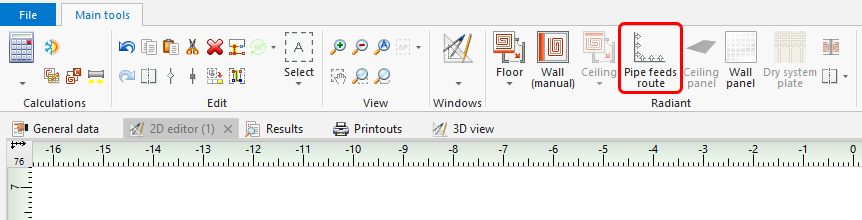
1. Pipe feeds route. - The Pipe-run component is available in the Distribution - thermal installations section on the Main tools toolbar for the enabled editing scopes: Rad.-floors,walls, Rad.-ceilings or Convectional.
The Pipe feed component is inserted using the Pipe-run or Pipe run pair component. Distinguishing between Pipe feed and Pipe-run is done automatically depending on whether it is connected to a Heating/Cooling Zone or to other component.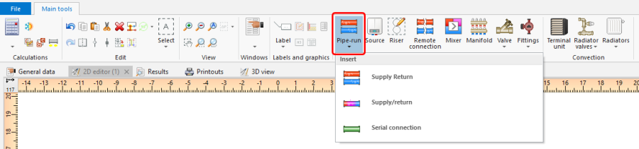
2. Pipe-run.


Example of use
Pipe feeds route - automatic generation of pipe feeds
Important properties
- Number of generated pipe feed pairs - the program automatically generates the number of required pipe feed pairs depending on the number of Heating/Cooling areas formed after division of the connected Heating/Cooling Zone.
- Pipe feed orientation in relation to section of pipe feed route - indicates on which side of the section of Pipe feeds route should the pipe feeds be generated.
- Manner of pipe feeds spacing determination:
'Auto' - initial value of pipe feeds spacing same as determined for the zone, is automatically compacted in case of problems with pipe feeds arrangement
'From H/C Zone' - according to pipe feeds spacing determined for the zone
'User specified' - according to specified pipe feeds spacing
'Acc. to band - max. width' - according to pipe feeds spacing determined/specified, not to exceed max. band width
'Acc. to band - fill with pipe feeds spacing available for the system' - pipe feeds spacing will be determined from available for the system to fill band width
'Acc. to band - fill ' - pipe feeds spacing will be determined from relation: Band width/number of pipe feeds
Note: specify Band width for:- Acc. to band - max. width,
- Acc. to band - fill with pipe feeds spacing available for the system
- Acc. to band - fill
or move the border of the band manually.
- VA in target H/C area - Spacing between pipe feeds that will be arranged in areas to which this pipe feeds route connects. This can be determined automatically or specified manually.
- Pipe spacing in insulation layer - can be determined automatically or specified manually.
- Insulation - pipe feed insulation.
- % output used - percentage of utilized output of pipe feeds running across the Heating/Cooling Zone.
Connecting to Manifold
The first segment of Pipe feeds route should be connected to any point on the axis of the manifold (between the flow rail and return rail). Pipe feeds will be generated automatically in proper sequence and with min. spacing coresponding to the distance between connection points on the manifold rail.
Arrangement of the Pipe feeds route
The arrangement of the Pipe feeds route is facilitated by using the operating modes ORTO and AUTO. We recommend to draw the Pipe feeds route along the walls.
Connecting to Heating/Cooling Zone
Point of connection of Pipe feeds route to Heating/Cooling Zone, the so-called "wifi" antenna - indicates the point where the specified Heating/Cooling Zone is connected to Pipe feeds route.
- Correction of connection of Pipe feeds route with Heating/Cooling Zone.
After making proper connection within the connected Heating/Cooling Zone, a "wifi" antenna symbol appears. If there is no "wifi" antenna symbol at the connection point, drag the hot-point at the end of the Pipe feeds route section with the left mouse button pressed on the edge of Heating/Cooling Zone area until green highlighting appears. Release the left mouse button. It is possible to connect one section of Pipe feeds route to the corner of several adjacent Heating/Cooling Zones (see the video).
- Disconnecting Pipe feeds route from Heating/Cooling Zone.
If the connection point has been set improperly, it can be modified manually. To disconnect Pipe feeds route, follow the operations described above with the SHIFT key pressed - the green highlighting will disappear and upon releasing the left mouse key the section will be disonnected (see the video).
For more information, see: Pipe feeds route - Good practices and use cases.
Manual arrangement of pipe feeds
Pipe feeds route - manual correction of automatically generated pipe feeds route
Automatic generation of pipe feeds can be disabled in the pop-up menu of Pipe feeds route available upon right clicking. This implies:
- disabling automatic division of Heating/Cooling Zone (a relevant message is displayed),
- disabling that mode also for subsequent sections of Pipe feeds route,
- loss of manual settings of properties made for this section (these sections) of Pipe feeds route.
Automatic generation of pipe feeds can be enabled at any moment of project creation.
Pipe feeds - manual arrangement of pipe feeds using a Pipe-run pair
- It is recommended to arrange pipe feeds manually after the Heating/Cooling Zone is finally divided into Heating/Cooling areas. Connecting a Heating/Cooling Zone using a pipe-run pair disables the automatic division of Heating/Cooling Zone.
Additional information
- Conflicts between automatically and manually arranged pipe feeds are not checked and are not diagnosed by the program.
| If you have any comments on this article, please send us a short message at info@instalsoft.com. |
|---|