Appending drawings with radiant system loops
Revision as of 18:49, 17 October 2015 by Translator EN (talk | contribs) (→Ręczna edycja rysunków pętli)
| Product | InstalSystem 5 |
| Type of article | FUNCTIONALITY |
| Source for translation | IS 5.0 Beta 21 |
Description
The Heating-cooling surface component (floors and ceilings) can be appended with drawings of loops. Drawings generated automatically by the program are refreshed each time the project is recalculated. It is possible to modify or append them and loops can be drawn manually. Manual editing is recommended at the final stage of design.
Location in the program
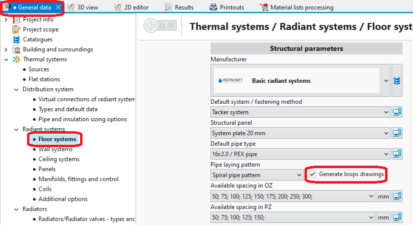
- General data - automatic generation of loops can be enabled for all components by selecting checkbox Generate loops drawings.
1. Loops drawings - General data - Data table for component Heating/Cooling Floor Zone, when working in the Rad.-floors,walls/Rad.-ceilings editing range, enables:
- automatic generation of loops by selecting checkbox Generate loops drawings; loop generation can be disabled here for a selected component when this checkbox is selected in General data,
- selection of pipe laying pattern.
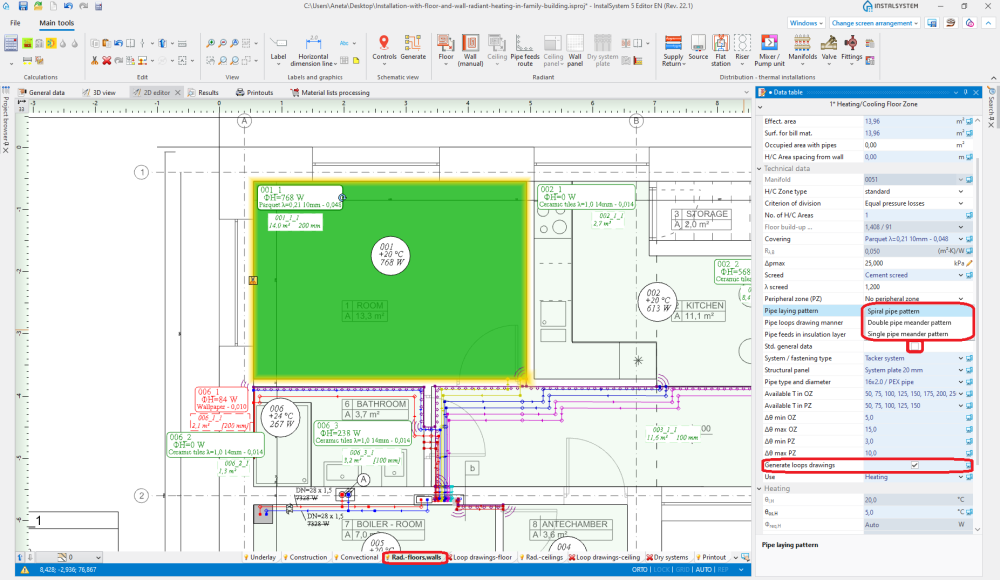
2. Pipe laying pattern
- The RHC loop tool available in Main tools, when working in the Loop drawings-floor/Loop drawings-ceiling editing range, enables manual drawing of loops. Use of this tool is recommended with the GRID mode enabled.
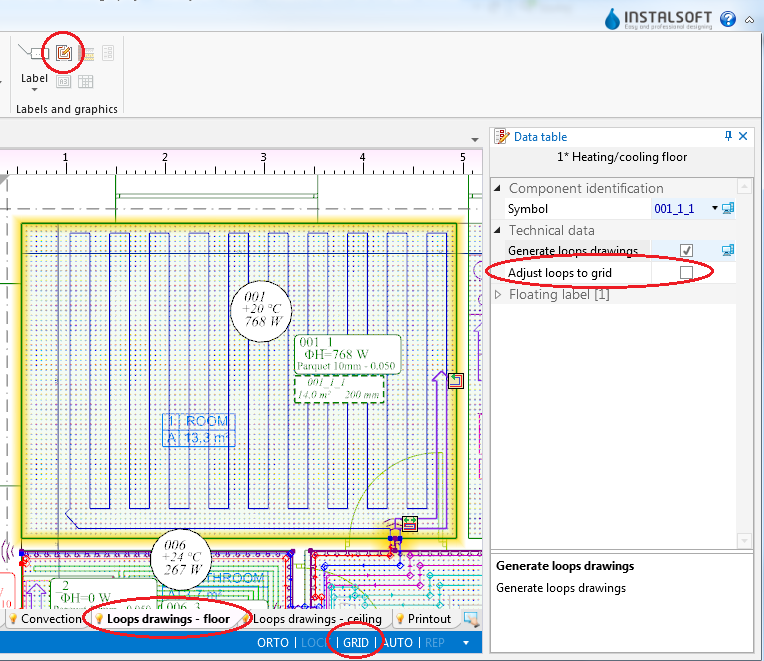
3. Loop drawings - Graphical editing


Example of use
Automatic generation of loop drawings
- Enable generation of loop drawings in general data or for selected components.
- Other than default pipe laying pattern can optionally be selected for selected components.
- Select the editing range Loop drawings-floor/Loop drawings-ceiling
- Indicate the pipe laying direction for the individual loops. This is done by means of Graphic indicators which are enabled after selecting Heating-cooling surface. In the case of Spiral pipe pattern, indicator
 for changing direction of pipe laying is available. To reposition the indicator, press and hold the LMB on the indicator and drag it with the purple arrow in the desired direction of pipe laying. In the case of Single pipe meander pattern/Double pipe meander pattern, two indicators are available: for changing direction of pipe laying and for selecting the side parallel to the meandering direction
  .
. - Recalculate the project
 . After recalculation the drawings of the loops are generated automatically.
 - If necessary, correct the pipe laying direction by relocating the graphic indicators and recalculate the project to refresh the loop drawings.


Manual editing of loop drawings
- Disable generation of loop drawings for selected components Heating-cooling surface.
Attention! Clearing the Generate loops drawings option does not remove existing drawings of loops, it only freezes them in their current state and enables manual editing or deleting thereof. - Enable the GRID mode which helps in correcting or manual drawing of loops. Grid nodes are arranged at the minimum distance allowable for the selected pipe laying pattern. Colours of grid nodes are repeated for the current pipe spacing, which facilitates drawing with the use of that spacing. The grid can be arranged parallel to selected edge of component Heating/Cooling Floor Zone by positioning on that edge the blue hot-point
 . It becomes available when component Heating/Cooling Floor Zone is selected.
 - Correct/draw manually selected segments of loop.

Additional information
- Styl graficzny - w celu zwiększenia czytelności wydruków pętli można:
- użyć stylu wyglądu elementów, w którym strefy powierzchni grzewczo-chłodzących są przezroczyste,
- wyłączyć widok konstrukcji lub usunąć podkład rysunkowy,
- wybrać sposobu prezentacji pętli jako różnokolorowe z przyłączami w kolorze pętli


- Diagnostyka - jeśli program nie będzie potrafił wygenerować rysunku pętli dla danego elementu, w oknie diagnostyki pojawi się ostrzeżenie. W celu jego wyeliminowania należy zweryfikować parametry układania lub odznaczyć checkbox Generate loops drawings i zmodyfikować rysunek ręcznie. Ręczna modyfikacja może być również rozwiązaniem w sytuacji, gdy forma rysunku generowanego automatycznie nie odpowiada oczekiwaniom użytkownika.