Appending drawings with radiant system loops
Revision as of 09:02, 18 February 2017 by X - JW edytor (talk | contribs) (→Manual editing of loop drawings)
| Product | InstalSystem 5 |
| Type of article | FUNCTIONALITY |
| Source for translation | BETA REV. 0.0.B21 |
Description
The Heating-cooling surface component (floors and ceilings) can be appended with drawings of loops. Drawings generated automatically by the program are refreshed each time the project is recalculated. It is possible to modify or append them and loops can be drawn manually. Manual editing is recommended at the final stage of design.
Location in the program
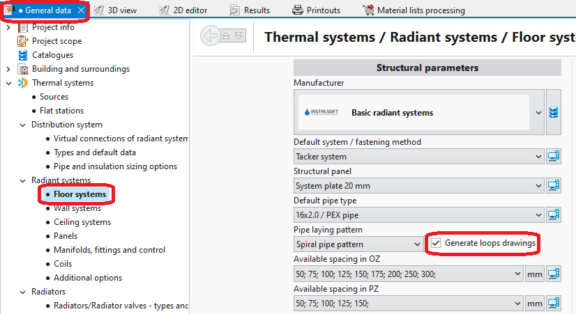
- General data - automatic generation of loops can be enabled for all components by selecting the Generate loops drawings checkbox.
1. Loops drawings - General data - Data table for component Heating/Cooling Floor Zone, when working in the Rad.-floors,walls/Rad.-ceilings editing range, enables:
- automatic generation of loops by selecting the Generate loops drawings checkbox; loop generation can be disabled here for a selected component when this checkbox is selected in General data,
- selection of pipe laying pattern.
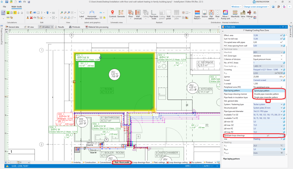
2. Pipe laying pattern
- The RHC loop tool available in Main tools, when working in the Loop drawings-floor/Loop drawings-ceiling editing range, enables manual drawing of loops. Use of this tool is recommended with the GRID mode enabled.
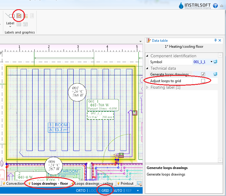
3. Loop drawings - Graphical editing


Example of use
Automatic generation of loop drawings
- Enable generation of loop drawings in general data or for selected components.
- Przeliczyć projekt
 . Po przeliczeniu projektu program automatycznie wygeneruje rysunki pętli.
 - Zmienić kierunek układania pętli (opcjonalnie).
Po zaznaczeniu elementu Heating-cooling surface dostępne są hotpointy kierunku układania pętli , a dla wariantu ułożenia Single pipe meander pattern/Double pipe meander pattern dodatkowo wskaźnik
  pozwalający na wskazanie boku wzdłuż którego będzie się odbywać meandrowanie. Aby widoczny był efekt zmiany kierunku układania pętli oraz wskazania innego boku tego układania, wymagane jest ponowne przeliczenie pliku.


Manual editing of loop drawings
- Disable generation of loop drawings for selected components Heating-cooling surface.
Attention! Clearing the Generate loops drawings option does not remove existing drawings of loops, it only freezes them in their current state and enables manual editing or deleting thereof. Całkowite usunięcie rysunków pętli jest możliwe po zaznaczeniu pętli poprzez dwukrotne kliknięcie lewym przyciskiem myszy na dowolnym odcinku pętli i wykonaniu operacji Usuń zaznaczone elementy. - Enable the GRID mode which helps in correcting or manual drawing of loops. Grid nodes are arranged at the minimum distance allowable for the selected pipe laying pattern. Colours of grid nodes are repeated for the current pipe spacing, which facilitates drawing with the use of that spacing. The grid can be arranged parallel to selected edge of component Heating/Cooling Floor Zone by positioning on that edge the blue hot-point
 . It becomes available when component Heating/Cooling Floor Zone is selected.
 - Correct/draw manually selected segments of loop.
- Narysowana pętla musi całkowicie zawierać się w elemencie Powierzchnia grzewczo - chłodząca i kończyć na jego krawędzi.

Additional information
- Graphic style - in order to improve the legibility of loop printouts, one can:
- use component appearance style where zones of heating/cooling surfaces are transparent,
- disable structure display or remove base drawing,
- select manner of loop display where loops differ in colour and pipe feeds are of the same colour as the corresponding loops


- Diagnostics - when the program is not able to generate a loop drawing for a given component, a warning is displayed in the diagnostics window. To rectify this, either the pipe laying parameters have to be adjusted or the Generate loops drawings checkbox must be cleared and the drawing modified manually. Manual modification may also be applied when the automatically generated drawing does not satisfy the user's expectations.