Creating network profiles: Difference between revisions
Jump to navigation
Jump to search
Klintsevicho (talk | contribs) |
Klintsevicho (talk | contribs) |
||
| Line 31: | Line 31: | ||
====Define required network profiles==== | ====Define required network profiles==== | ||
* Add to the project and configure the ''<IS_TS id=ProfileGroupAutomatyczne/>'' worksheets in the ''<IS_TS id=rsDanogi/>'' window: | * Add to the project and configure the ''<IS_TS id=ProfileGroupAutomatyczne/>'' worksheets in the ''<IS_TS id=rsDanogi/>'' window: | ||
** (Optionally) | ** (Optionally) Select the ''<IS_TS id=ConfigurationProfilesAppereance/>'', | ||
** (Optionally) | ** (Optionally) Change the ''Scale'' , ''<IS_TS id=strPoziomPorownawczyPure/>'' , ''<IS_TS id=strLblOdstepPomiedzyCzesciamiCaption/>'' and ''<IS_TS id=SzerokoscTabelkiProfiluCaption/>'' for the ''<IS_TS id=strArkuszRoboczy/>''.<br/>{{#ev:youtube|OlbOSjZSwzk|900||||rel=0}} | ||
====Define profiles routs==== | ====Define profiles routs==== | ||
Revision as of 11:56, 30 June 2026
| Product | NetSystem 5 |
| Type of article | Functions and tools |
| Source for translation | 2026-05-04 |
Description
This article describes the methods of creating Profiles of Water supply networks and Sewage networks.
The profile creation feature allows to:
- automatically generate network profiles based on the prepared network. Profiles are created according to user-defined routes. The appearance can be manually configured.
- manually create network profiles without performing calculations.
Location in the program
- Icons of components and functions for the Profiles creation are available on the Main tools bar in the Profiles section when Water supply networks or Sewage networks scope is active:
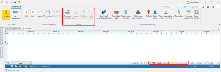
1. Profiles icons of components and functions. - List of all created in a project Profiles worksheets is displayed in the graphic view management window.

2. List of Profiles worksheets.


Examples of use
Basic scenario - generating Automatic profiles
Define required network profiles
- Add to the project and configure the Automatic profiles worksheets in the General data window:
- (Optionally) Select the Configuration of the profiles appearance ,
- (Optionally) Change the Scale , Reference level , Spacing between profiles and Width of the profile table for the Worksheet.
Define profiles routs
- In the 2D editor window open Project browser and select Profiles Water supply networks or Profiles Sewage networks scope;
- Choose Automatic profiles / Profile route definitions;
- Add a profile route, specifying in the Data table window:
- From worksheet - the Name of Worksheets with maps from which the profile will be generated,
- On the worksheet - the Name of Worksheets with profiles on which the profile will be generated.
Note: Multiple profiles routes can be added to a single Profile Worksheet. They are displayed sequentially, using the distance defined for the Profile in the Spacing between profiles field. - Start des. - select start destination from the list,
- End des. - select end destination from the list.
Note: The specified route will be highlighted on the Map so its correctness can be verified. - (Optionally) Change Start type - Normal or Compacted.
Generate profiles
- Run the function Generate profiles,
- Open the generated profile on the corresponding worksheet.

3. Generate profiles.

(Optionally) Modification or creation of a new profile configuration
In the General data window / Component appearance and descriptions configuration / Configuration of the profiles appearance :

- Modify the existing or add new Configuration of the profiles appearance ;
- Select the data displayed in the profile table;
- Configure individual rows of the profile data table in terms of Data font, Line colour, Text orientation, etc.;
- Define Combined field;
- Determine the settings for the presentation of Colliding network on profile;
- Configure the Profile drawing appearance regarding:
- Draw existing area,
- Show additional junction description,
- Definition of the way of manholes drawings:
- Simplified manhole drawings,
- Draw manholes as closed solid.
- Definition of the way of pipe-run drawings:
- single line - if the checkbox Draw a single line is ON,
- pipeline cross-section - if the checkbox Draw a single line is OFF.
- Drawing Trenches:
- Bedding (Sections of network),
- Backfill (Sections of network),
- Bedding Manholes.
- Specify whether to display collision data by checking or unchecking the Show data of collisions checkbox;
<
5. Show data of collisions. - Determine the Presentation on the profile of Route direction changes and indicate the necessity to Describe route direction change angles.

In the 2D editor / Data table window:
- Change the Reference level for the selected Water pipeline profile section or Sewerage profile section.

6. Reference level.

In the 2D editor / Project browser window:
- Change the order of presentation Route of the profile using Swap function.

7. Swap function.

Note: After changes perform Generate profiles once again.
Additional scenario - creating Manual profiles
Define required network profiles
- Add to the project and configure the Manual profiles worksheets in the General data window - steps to perform like in Basic scenario,
Define profiles routs
- The command icons for creating Manual profiles are enabled when the corresponding worksheet is selected:

8. Manual profiles command icons.
- Insert Profile start or Contracted profile start and indicate:
- At section end - the element on the end of the section,
- Flow direction,
- Elevation of area under design,
- Elevation of existing area,
- Pipeline axis elevation for Water pipe network junction.
- Insert Profile section (this can be using hotpoint, as well) and indicate:
- At section end - the element on the end of the section,
- Length of the section,
- Flow direction,
- Elevation of area under design,
- Axis elevation, pt. 1 and Axis elevation, pt. 2 - the elevation of the pipe-run axis at the starting and ending points of the section.
- (Optionally) Set the information about Side inlets using Add new row function;

9. Side inlets. - (Optionally) Adjustment of particular Profile section with additional elements:
- Colliding network,
- Protection tube,
- Gate valve (only for Water supply networks),
- Local Trenches.
- Insert Profile start or Contracted profile start and indicate:
- Change the Reference level for the selected Water pipeline profile section or Sewerage profile section.


(Optionally) Modification or creation of a new profile configuration
Steps to perform like for the "Basic scenario - generating Automatic profiles": (Optionally) Modification or creation of a new profile configuration.
Scale mark
- The element Scale mark is available on Automatic profiles and Manual profiles worksheets for Water supply and sewage networks;

10. Scale mark. - The element is not tied to the profile drawing - it can be inserted anywhere on the worksheet and freely moved;
- The displayed on the Scale mark values of Horizontal scale and Vertical scale are consistent with the data specified in the General data window and are automatically updated with changes to the scale of the worksheet on which the element is placed;
- The Font and the Element style can be modified.
