Creating network profiles: Difference between revisions
Jump to navigation
Jump to search
Klintsevicho (talk | contribs) No edit summary |
Klintsevicho (talk | contribs) No edit summary |
||
| Line 84: | Line 84: | ||
* The element ''<IS_TS id=ScaleMark/>'' is available on ''<IS_TS id=ProfileGroupAutomatyczne/>'' and ''<IS_TS id=rpProfileReczne/>'' worksheets for ''<IS_TS id=PH_NS5_SAN/>'';<br/>[[File: Creating network profiles Scale mark.png|900 px|left|thumb|10. <IS_TS id=ScaleMark/>.]]<br clear="all"/> | * The element ''<IS_TS id=ScaleMark/>'' is available on ''<IS_TS id=ProfileGroupAutomatyczne/>'' and ''<IS_TS id=rpProfileReczne/>'' worksheets for ''<IS_TS id=PH_NS5_SAN/>'';<br/>[[File: Creating network profiles Scale mark.png|900 px|left|thumb|10. <IS_TS id=ScaleMark/>.]]<br clear="all"/> | ||
* The element is not tied to the profile drawing - it can be inserted anywhere on the sheet and moved freely; | * The element is not tied to the profile drawing - it can be inserted anywhere on the sheet and moved freely; | ||
* The displayed on the ''<IS_TS id=ScaleMark/>'' values are consistent with the data specified in the ''<IS_TS id=rsDanogi/>'' window | * The displayed on the ''<IS_TS id=ScaleMark/>'' values are consistent with the data specified in the [[Creating_network_profiles#Define_required_network_profiles | ''<IS_TS id=rsDanogi/>'']] window; | ||
Revision as of 13:25, 27 April 2026
| Product | NetSystem 5 |
| Type of article | Functions and tools |
| Source for translation | 2026-04-13 |
Description
This article describes the methods of creating Profiles of Water supply networks and Sewage networks.
The profile creation feature allows to:
- automatically generate network profiles based on the prepared network. Profiles are created according to user-defined routes. The appearance can be manually configured.
- manually create network profiles without performing calculations.
Location in the program
- Icons of components and functions for the Profiles creation are available on the Main tools bar in the Profiles section when Water supply networks or Sewage networks scope is active:
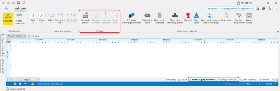
1. Profiles icons of components and functions. - List of all created in a project Profiles is displayed in the graphic view management window.

2. Profiles list.


Examples of use
Basic scenario - generating Automatic profiles
Define required network profiles
- Add to the project and configure the Automatic profiles worksheets in the General data window:
- (Optionally) Change the scale, reference level, spacing between profiles for the worksheet, and profile table width,
- (Optionally) Select the profile appearance configuration for the worksheet.
Define profiles routs
- In the 2D editor window open Project browser and select Profiles Water supply networks or Profiles Sewage networks scope;
- Choose Automatic profiles / Profile route definitions;
- Add a profile route, specifying in the Data table window:
- From worksheet - the Name of Worksheets with maps from which the profile will be generated,
- On the worksheet - the Name of Worksheets with profiles on which the profile will be generated,
- Start des. - select start destination from the list,
- End des. - select end destination from the list.
Note: The specified route will be highlighted on the Map so its correctness can be verified. - (Optionally) Change Start type - Normal or Compacted.
Generate profiles
- Run the function Generate profiles,
- Open the generated profile on the corresponding worksheet.
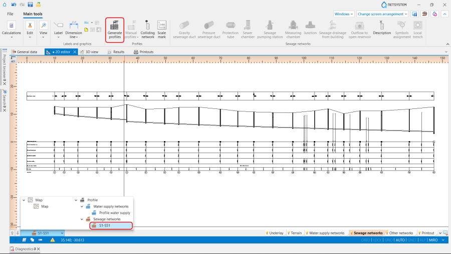
3. Generate profiles.

(Optionally) Modification or creation of a new profile configuration
In the General data window / Component appearance and descriptions configuration / Configuration of the profiles appearance :
- Modify the existing or add new Configuration of the profiles appearance ;
- Select the data displayed in the profile table;
- Configure individual rows of the profile data table in terms of Data font, Line colour, Text orientation, etc.;
- Define Combined field;
- Define the settings for the presentation of Colliding network on profile;
- Configure the Profile drawing appearance regarding:
- Draw existing area,
- Show additional junction description,
- Definition of the way of manholes drawings:
- Simplified manhole drawings
- Draw manholes as closed solid
- Definition of the way of pipe-run drawings:
- single line - if the box Draw a single line is ON
- pipeline cross-section - if the box Draw a single line is OFF,
- Drawing Trenches:
- Bedding (Sections of network)
- Backfill (Sections of network)
- Bedding Manholes
<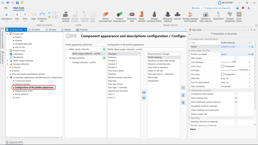
4. Configuration of the profiles appearance .
- Determine the Presentation on the profile of Route direction changes and indicate the necessity to Describe route direction change angles.

In the 2D editor / Data table window:
- Change the Reference level for the selected Water pipeline profile section or Sewerage profile section.
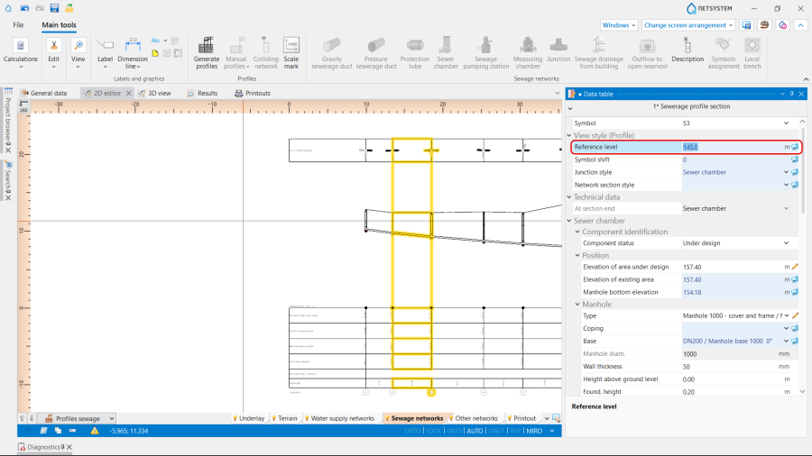
5. Reference level.

In the 2D editor / Project browser window:
- Change the order of presentation Route of the profile using Swap function.
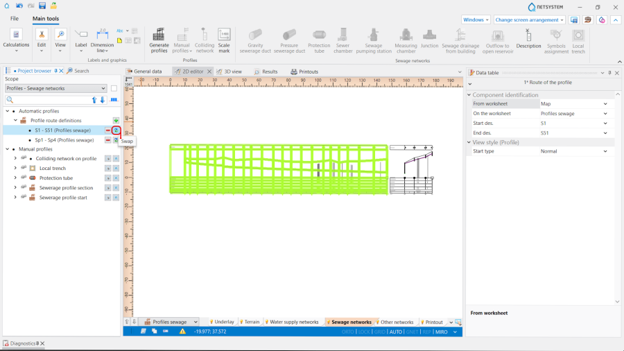
6. Swap function.

Note: After changes perform Generate profiles once again.
Additional scenario - creating Manual profiles
Define required network profiles
- Add to the project and configure the Manual profiles worksheets in the General data window - steps to perform like in Basic scenario.
Scale mark
- The element Scale mark is available on Automatic profiles and Manual profiles worksheets for Water supply and sewage networks;

10. Scale mark. - The element is not tied to the profile drawing - it can be inserted anywhere on the sheet and moved freely;
- The displayed on the Scale mark values are consistent with the data specified in the General data window;
