Pipe-run: Difference between revisions
| Line 44: | Line 44: | ||
===Determining the vertical alignment of the pipe-runs - <IS_TS id=InstalacjeGrzewcze/>, <IS_TS id=InstalacjeChlodnicze/> and <IS_TS id=InstalacjeWodociagowe/>=== | ===Determining the vertical alignment of the pipe-runs - <IS_TS id=InstalacjeGrzewcze/>, <IS_TS id=InstalacjeChlodnicze/> and <IS_TS id=InstalacjeWodociagowe/>=== | ||
The alignment and elevations of a pipe-run can be managed using dedicated editors that are | The alignment and elevations of a pipe-run can be managed using dedicated editors that are displayed after selecting a component in the ''<IS_TS id=GraphicalEdit/>'' and ''<IS_TS id=View3D/>'' window: | ||
* [[File:Rzedna_konca_dzialki-new.png|40px|]] - shows the elevation of the pipe-run end. | * [[File:Rzedna_konca_dzialki-new.png|40px|]] - shows the elevation of the pipe-run end. | ||
* [[File:Rzedna-odcinka-new.png|40 px|]] - shows the elevation of the section. | * [[File:Rzedna-odcinka-new.png|40 px|]] - shows the elevation of the section. | ||
| Line 54: | Line 54: | ||
** The value of ''<IS_TS id=strRzednaLong/>'' can be modified in the ''<IS_TS id=DataEditorTable/>'' window for the ''<IS_TS id=iNameDzialka/>'' and this change automatically modifies the values in all editors for the selected component. <br/> {{#ev:youtube|aN3ZDoXeBsQ|900||||rel=0}} <br clear="all"/> | ** The value of ''<IS_TS id=strRzednaLong/>'' can be modified in the ''<IS_TS id=DataEditorTable/>'' window for the ''<IS_TS id=iNameDzialka/>'' and this change automatically modifies the values in all editors for the selected component. <br/> {{#ev:youtube|aN3ZDoXeBsQ|900||||rel=0}} <br clear="all"/> | ||
* ''<IS_TS id=PiperunElevationOptionsManualBySegments/>'' mode: | * ''<IS_TS id=PiperunElevationOptionsManualBySegments/>'' mode: | ||
** In | ** In the editors available in the ''<IS_TS id=GraphicalEdit/>'' and ''<IS_TS id=View3D/>'' window it is possible to specify the elevation and distance from the floor of a pipe-run section. | ||
** Based on the difference between the specified section elevations, vertical pipe-runs are automatically created. | ** Based on the difference between the specified section elevations, vertical pipe-runs are automatically created. | ||
** Editors of pipe-runs connected on one end to terminal units are greyed out and these cannot be edited. | ** Editors of pipe-runs connected on one end to terminal units are greyed out and these cannot be edited. | ||
Revision as of 16:30, 16 January 2023
| Product | InstalSystem 5 |
| Type of article | FUNCTIONS AND TOOLS |
| Source for translation | 2022-03-24 |
Description
Pipe-run is a component that is available within all design scopes, it forms a fragment of the piping system between two junctions where the flow can be changed. Within the following scopes: Heating systems, Cooling systems and Water supply systems a Pipe-run may consist of multiple segments (vertical and horizontal), separated by pipe-run division points. It can be drawn as a single pipe-run or as a Pipe-runs pair/ Three pipe-runs. Within the Sanitary drainage systems scope a Pipe-run of the Gravity sewerage or Ventilation conduit type always consists of a single segment.
It is possible to specify default values for Distance from floor (set in storey data). In addition, the user has full control over the arrangement of the pipe-runs using dedicated editors available in the 2D editor and 3D view windows.
Location in the program
Inserting pipe-runs
- Icons associated with Pipe-run, with Project scope: Heating systems or Cooling systems activated, are available in the 2D editor window in the Main tools bar, section Distribution - thermal installations when the following editing scopes are enabled: Convectional, Rad.-floors,walls or Rad.-ceilings.
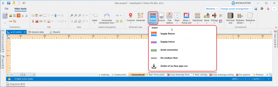
1. Pipe-run - Heating systems or Cooling systems. - Icons associated with Pipe-run, with Water supply systems activated, are available in the 2D editor window in the Main tools bar, section Distribution - Water supply when the Water supply editing scope is enabled.

2. Pipe-run - Water supply systems. - Icons associated with Pipe-run, with Sanitary drainage systems activated, are available in the 2D editor window in the Main tools bar, section Sanitary drainage when the Drainage (S) editing scope is enabled.

3. Pipe-run - Sanitary drainage systems.


Examples of use
Pipe-run dividing point and midpoint
- One Pipe-run may consist of several sections connected by means of midpoints.
- Two Pipe-run are separated by a pipe-run dividing point - a junction/node.
- Any number of additional points can be placed on a Pipe-run using the context menu and functions available there: Insert midpoint and Insert dividing point.
- Midpoints can be changed into dividing points and vice versa:
Default distances between pipe-run and floor and between pipe-run and ceiling
In the Data table window it is possible to specify for a Storey the default distance from the floor separately for each Pipe-run type component and the default distance from the ceiling (for arranging ceiling panels) in the following fields:
- for Heating systems:
- ΔHpipe-run,,S and ΔHpipe-run,, R - Default distance of pipe-runs (except for supplying ceiling panels) from the floor specified in storey data: S - supply, R - return.
- ΔHpipe-run,pan. - Pipe-run to ceiling distance - ceiling panel distribution.
- for Water supply systems:
- ΔHpipe-run,,HW - Default pipe-run distance from the floor (set in storey data) for Pipe-run: Hot water.
- ΔHpipe-run,,CW - Default pipe-run distance from the floor (set in storey data) for Pipe-run: Cold water.
- ΔHpipe-run,,Circ - Default pipe-run distance from the floor (set in storey data) for Pipe-run: Circulation.

4. Default pipe-run distance.

Pipe-run laying distance
- The Distance between pipe-runs can be specified for Pipe-runs pair/Three pipe-runs in the Data table window. After each component inserted, the last specified Distance is memorized.

5. Distance for Pipe-runs pair.

Determining the vertical alignment of the pipe-runs - Heating systems, Cooling systems and Water supply systems
The alignment and elevations of a pipe-run can be managed using dedicated editors that are displayed after selecting a component in the 2D editor and 3D view window:
 - shows the elevation of the pipe-run end.
 - shows the elevation of the section.
 - shows the distance between pipe-run point/section and floor.
6. Display of the elevations of a Pipe-run in the 2D editor and 3D view window.

InstalSystem 5 offers three methods of managing the alignment of a distribution system that allow the most convenient method to be selected to suit the individual design context. The method should be selected in the Vertical layout of pipe-run editor in the Data table window for the Pipe-run:
- Auto mode:
- Editors showing the elevation of pipe-run ends and distance from the floor are greyed out and the values presented cannot be modified.
- The value of Elevation can be modified in the Data table window for the Pipe-run and this change automatically modifies the values in all editors for the selected component.
- Manual elevations of sections mode:
- In the editors available in the 2D editor and 3D view window it is possible to specify the elevation and distance from the floor of a pipe-run section.
- Based on the difference between the specified section elevations, vertical pipe-runs are automatically created.
- Editors of pipe-runs connected on one end to terminal units are greyed out and these cannot be edited.
- The 2D editor and 3D view windows do not display editors with elevations of vertical sections of pipe-runs.

7. Vertical layout of pipe-run - Manual elevations of sections.
- Manual elevations of nodes:
- Editors in the 2D editor and 3D view window enable specifying the elevations and distance from the floor of the ends of a Pipe-run section.
- Vertical sections of pipe-runs are NOT automatially created - the entire pipe-run layout is controlled by the user.
- Editors of pipe-runs connected on one end to terminal units are greyed out and these cannot be edited.

8. Vertical layout of pipe-run - Manual elevations of nodes.


Attention! Every change of elevations and modification of Pipe-run layout requires running a Check connections operation available on the Main tools bar in section Calculations.
Determining the vertical alignment of pipe-runs - Sanitary drainage systems
The elevations and gradient of a pipe-run can be managed using dedicated editors that are displayed after selecting a component in the 2D editor and 3D view window:
 - shows the elevation of pipe-run sections, values presented in the editors correspond to the fields: Elevation of first node and Elevation of second node available in the Data table window of the component.
 - shows the gradient of the pipe-run and corresponds to the Real gradient field available in the Data table window of the component.
5. Display of elevations and gradient of a Pipe-run in the 2D editor and 3D view window.

When laying the pipe-runs, they adopt a gradient according to the direction of flow to the sewage outlet, taking into account the settings made in the General data window on the Sanitary drainage systems/ Calculation standards and options tab:
- The default minimum gradients specified for the selected component locations are adopted. In addition, the pipe-run laying algorithm takes into account the elevation and gradient values specified by the user in the editors described above.
- The Method of conducting of branches is taken into account:
- for the towards the floor setting - pipe-runs are arranged towards the terminal units with minimum gradient. If necessary, vertical pipe-runs at the terminal units are added taking into account the value specified in Distance from the floor of the connection points to the stack field,
- for the towards the wall setting - pipe-runs are arranged downstream of the terminal unit with the gradients specified in the General data window, and they are then connected to the collective branch by means of a vertical pipe-run (if drawing it is necessary for the continuity of the system).

9. Alignment of pipe-runs - Sanitary drainage systems.

Prowadzenie działek w jednej płaszczyźnie pionowej
- Odpowiednie ustawienia wartości rzędnych poszczególnych typów działek w oknie Data table dla elementu Storey w sekcjach: Heating/Cooling bądź Water supply oraz narzucenie minimalnej wartości w polu Distance w oknie Data table elementu Pipe-runs pair/ Trójka działek pozwalają na poprowadzenie działek w jednej płaszczyźnie pionowej, np. w ścianie jedna nad drugą.
Działki skośne
- Dzięki funkcji Vertical layout of pipe-run program umożliwia pełną kontrolę nad przebiegiem działki, co wraz z możliwością dowolnego dodawania punktów na element umożliwia rysowanie działek skośnych i projektowanie podłączeń elementów instalacji umieszczonych na skośnych poddaszach budynów.
Podstawowe zasady łączenia działek z innymi elementami instalacji
Na pasku Main tools w grupie Edit dostępne są trzy możliwości automatycznego podłączania odbiorników do narysowanego uprzednio rozprowadzenia działek instalacji:

- Automatically connect terminal units - operacja łączy zaznaczone elementy Pipe-run i odbiorniki dla zakresów: Heating systems, Cooling systems i Water supply systems.
- Automatically connect terminal units in tee system - operacja łączy zaznaczone elementy Pipe-run i odbiorniki instalacji wodociągowej w systemie podłączeń trójnikowych.
- Connect in series - operacja łączy zaznaczone przed jej wywołaniem elementy Ceiling panel lub Wall panel działką typu Serial connection. For more information, see: Projektowanie panelowych (sufitowych, ściennych) instalacji grzewczych/chłodniczych.
Dla wszystkich elementów podłączanych do instalacji (np. Terminal unit, Mixer, Manifold), rysowany jest poziomy odcinek działki na odległość 5cm, a potem tworzone jest załamanie kierunku tak, aby przejść na określoną rzędną elementu Pipe-run. Wyjątek od tej reguły stanowią:
- Podłączenie elementu Radiator zintegrowany z zaworem kątowym - rysowany jest poziomy odcinek działki o długości: Distance from wall + 5cm, a potem tworzone jest załamanie kierunku, tak aby przejść na określoną rzędną elementu Pipe-run.
- Podłączenie elementu Water supply faucet - rysowany jest poziomy odcinek działki o długości 1cm, a potem tworzone jest załamanie kierunku tak, aby przejść na określoną rzędną elementu Pipe-run.

11. Podłączenie elementu Water supply faucet. - Podłączenie elementu Riser - jeżeli podłączenie działki jest prowadzone bezpośrednio do elementu bez punktów pośrednich, rzędna działki przyjmuje rzeczywistą wartość zgodnie z danymi w oknie Data table elementu Pipe-run.
- Podłączenie elementu Mixer/Control loop - wyniku operacji Automatically connect terminal units podłączane są tylko punkty znajdujące się po stronie pierwotnej elementu Mixer.

Działka w trybie auto
W sytuacji, gdy działki w projekcie zostały narysowane w taki sposób, że w ramach jednej kondygnacji występują działki pionowe (uzyskane nie poprzez wstawienie elementu Riser, a poprzez połączenie czterech działek bądź par działek), działki podłączane do tych pionowych odcinków podlegają określonym zasadom rysowania:
- Podczas rysowania elementów przy włączonym trybie pracy Pipe-run podłącza się do działki pionowej z zachowaniem swojej rzędnej.
- Podczas podłączania działki do działek, których współrzędne się pokrywają, rysowana Pipe-run zostanie podłączona do elementu o najniższej rzędnej.

12. Podłączenie do działek pionowych.
