Appending drawings with radiant system loops: Difference between revisions
| Line 25: | Line 25: | ||
**automatic generation of loops by selecting the ''<IS_TS id=GenerujRysunkiPetli/>'' checkbox; loop generation can be disabled here for a selected component when this checkbox is selected in ''<IS_TS id=rsDanogi/>'', | **automatic generation of loops by selecting the ''<IS_TS id=GenerujRysunkiPetli/>'' checkbox; loop generation can be disabled here for a selected component when this checkbox is selected in ''<IS_TS id=rsDanogi/>'', | ||
**selection of pipe laying pattern.<br/>[[File:Suf-loops-dem-zone.png|900 px|left|thumb|2. Pipe laying pattern]]<br clear="all"/> | **selection of pipe laying pattern.<br/>[[File:Suf-loops-dem-zone.png|900 px|left|thumb|2. Pipe laying pattern]]<br clear="all"/> | ||
*The ''<IS_TS id=WezownicaCaption/>'' tool available in ''<IS_TS id=NarzedziaGlowne/>'', when working in the ''<IS_TS id=RysPetliPodlogoweCaption/>''/''<IS_TS id=RysPetliSufitoweCaption/>'' editing range, enables manual drawing of loops. Use of this tool is recommended with the ''<IS_TS id=strAUTOModeName/>'' mode and ''<IS_TS id=strGRIDModeName/>'' mode enabled ( | *The ''<IS_TS id=WezownicaCaption/>'' tool available in ''<IS_TS id=NarzedziaGlowne/>'', when working in the ''<IS_TS id=RysPetliPodlogoweCaption/>''/''<IS_TS id=RysPetliSufitoweCaption/>'' editing range, enables manual drawing of loops. Use of this tool is recommended with the ''<IS_TS id=strAUTOModeName/>'' mode and ''<IS_TS id=strGRIDModeName/>'' mode enabled (the grid has two levels - large and small dots).<br/>[[File:Suf-loops-floor-screen_mod.png|900 px|left|thumb|3.Loop drawings - Graphical editing]]<br clear="all"/> | ||
==Example of use== | ==Example of use== | ||
Revision as of 20:28, 19 March 2022
| Product | InstalSystem 5 |
| Type of article | FUNCTION AND TOOL |
| Source for translation | 2022-03-15 |
Description
The Heating-cooling surface component (floors and ceilings) can be appended with drawings of loops. Drawings generated automatically by the program are refreshed each time the project is recalculated. It is possible to modify or append them and loops can be drawn manually. Manual editing is recommended at the final stage of design.
Location in the program
- General data - automatic generation of loops can be enabled for all components by selecting the Generate loops drawings checkbox.
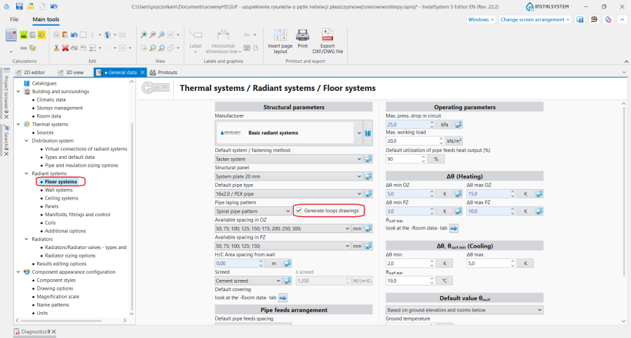
1. Generate loops drawings - Data table for component Heating/Cooling Floor Zone, when working in the Rad.-floors,walls/Rad.-ceilings editing range, enables:
- automatic generation of loops by selecting the Generate loops drawings checkbox; loop generation can be disabled here for a selected component when this checkbox is selected in General data,
- selection of pipe laying pattern.
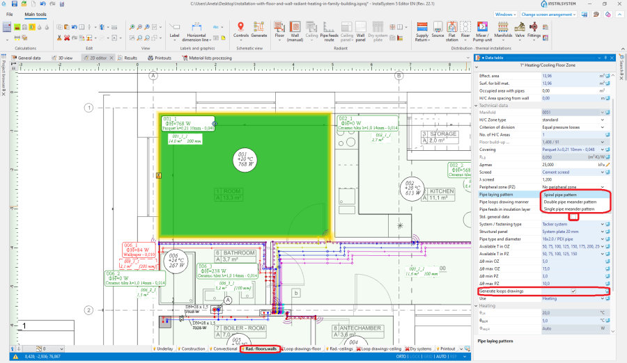
2. Pipe laying pattern
- The RHC loop tool available in Main tools, when working in the Loop drawings-floor/Loop drawings-ceiling editing range, enables manual drawing of loops. Use of this tool is recommended with the AUTO mode and GRID mode enabled (the grid has two levels - large and small dots).
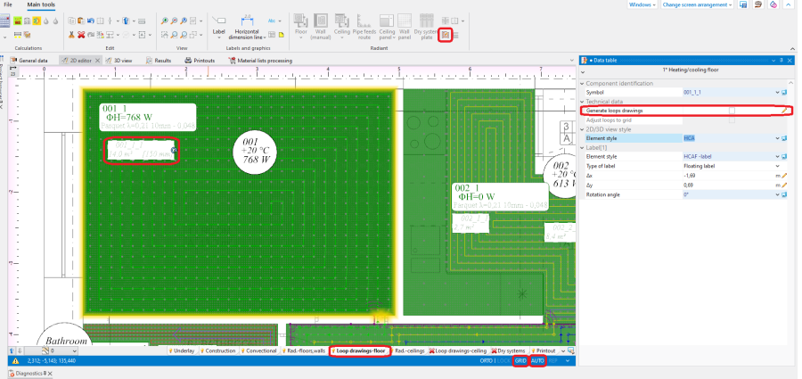
3.Loop drawings - Graphical editing


Example of use
Automatic generation of loop drawings
- Enable Generate loops drawings in General data window or for selected components.
- Calculate the project
 . Upon calculating the project, loop drawings will be generated automatically.
 - Change direction of loop arrangement (option).
After selecting Heating-cooling surface hotpoints of loop laying direction become available , and in the case of Single pipe meander pattern/Double pipe meander pattern a pointer is also available
  for indicating the side along which meandering is to be done. To display the effect of changing the loop laying direction and of indicating other side, the file must be recalculated.


- Skontrolować wypełnienie elementów Heating-cooling surface elementem RHC loop, w szczególności czy nie pozostały puste miejsca. Program umożliwia wypełnienie takich obszarów rurami z odstępem mniejszym niż wyliczony/narzucony dla strefy. Działanie mechanizmu można kontrolować na poziomie:
- całego projektu - w oknie General data na zakładkce Radiant systems - Additional options,

4. Sposób rysowania pętli dla całego projektu - elementu Heating/Cooling Floor Zone po zaznaczeniu tego elementu, w oknie Data table, w polu Pipe loops drawing manner.

5. Sposób rysowania pętli dla wybranego elementu Heating/Cooling Floor Zone
- całego projektu - w oknie General data na zakładkce Radiant systems - Additional options,


Manual editing of loop drawings
- Disable generation of loop drawings for selected components Heating-cooling surface.
Attention! Clearing the Generate loops drawings option does not remove existing drawings of loops, it only freezes them in their current state and enables manual editing or deleting thereof. To completely remove loop drawings double left click the loop and select Delete selected components. - Enable the GRID mode which helps in correcting or manual drawing of loops. Duże węzły grid are arranged at odległości wyliczonej/narzuconej dla danej powierzchni, małe węzły siatki are arranged at the minimum distance allowable for the selected pipe laying pattern. Colours of grid nodes are repeated for the current pipe spacing, which facilitates drawing with the use of that spacing. The grid can be arranged parallel to selected edge of component Heating/Cooling Floor Zone by positioning on that edge the blue hot-point
 . It becomes available when component Heating/Cooling Floor Zone is selected.
 - Correct/draw manually selected segments of loop.
- Zawrzeć narysowaną pętlę w całości w elemencie Heating-cooling surface i kończyć na jego krawędzi.

Ręczna edycja jest również konieczna w niektórych sytuacjach projektowych, gdy automatycznie wygenerowane rysunki pętli są niepoprawne. Do najczęściej spotykanych nieprawidłowości należą:
- krzyżowanie się początku i końca rysunku pętli,
- różne rozstawy rur w pętli,
- asymetrycznie rozmieszczone rysunki pętli w sąsiadujących elementach Heating-cooling surface,
- nieprawidłowe rysunki podpięcia pętli w punktach włączenia przyłączy.
W każdym z tych przypadków istnieje możliwość wykonania ręcznej korekty rysunku zgodnie z instrukcjami w filmach poniżej.
Krzyżowanie się początku i końca rysunku pętli
Zmiana kierunku rysowania pętli lub zmiana umiejscowienia podpięcia przyłączy.
Różne rozstawy rur w pętli
W sytuacji gdy Heating-cooling surface jest wypełniona w sposób nieprawidłowy (np. występują różne rozstawy rur w ramach jednej pętli lub sąsiadujące ze sobą powierzchnie zostały asymetrycznie wypełnione), należy:
- Zaznaczyć Adjust loops to grid w Data table elementu Heating-cooling surface
- Włączyć funkcję GRID
- Jeśli potrzeba, dokonać korekty wielkości elementu Heating-cooling surface.
Nieprawidłowe rysunki podpięcia pętli w punktach włączenia przyłączy
Zmiana położenia punktów podłączenia przyłączy.
Manual editing of loop drawings in dry systems with guide plates
- Manual editing of loops is the only way for designing correct loops in systems based on Dry system plate type components .
- In the case of dry floor systems with Dry system plate catalog components arranged in the program, the characteristic points of the plates take on the role of a grid.
- In dry systems with Dry system plate the use of the "drawing loop length" function is recommended.
For more information, see:How to include the drawing loop lenght in the calculations?
For more information, see: Inserting plates in dry floor heating system
Additional information
- RHC loop ma swoje własne miejsce w drzewie Component appearance and descriptions configuration. In order to improve the legibility of loop printouts, można w Coil configuration wybrać ustawienia:
- Different circuit colours
- Pipefeeds use same colour as coil.


- Loop drawings are not mandatory and they do not have to be complete if the Take into account in calculations: drawing loop length option has not been selected.
- In the case of virtual connections, automatically generated loops originate from arbitrary points indicated by the program. After pipe feeds are drawn, the starting points of loops are automatically relocated. The loop drawings can also be automatically modified due to the routes of pipe feeds to other areas/rooms being taken into account.
- Pipe laying pattern można zmienić dla całego projektu na zakładce General data lub dla pojedynczego elementu Heating/cooling floor.