Designing sanitary system loop installations
| Product | InstalSystem 5 |
| Type of article | DESIGNING LESSON |
| Source for translation | 2020-02-11 |
Scope of lesson
This lesson shows how to create a sanitary system loop installation. The latter is located in a single-family two-storey building with basement.
Modules and program configuration
- InstalSystem 5 software package with the following modules:
- Tap water systems
- Tap water extensions
- Recommended: sanitary system pipe catalogues containing direct U-shaped tap water connection, which guarantees lack of no-flow zones within the system
Project file
The project file used in this lesson: Water supply loop system in residential building (example for the lesson).
Initial state
The initial state file is located in the Project table, and it contains the building graphic structure and radiant sanitary system, which needs to be completed with a loop installation on the storey.
For more information, see: Design of water supply system installation
Steps to perform
Turning on the program and project general data configuration
- Turn the program on.
- Load the project file - Single-family building water installation initial state, isproj.
Installation edition
- Select storey No. 1.
- Draw hot and cold water pipe feeds, so that a loop installation is created in room 1.5.
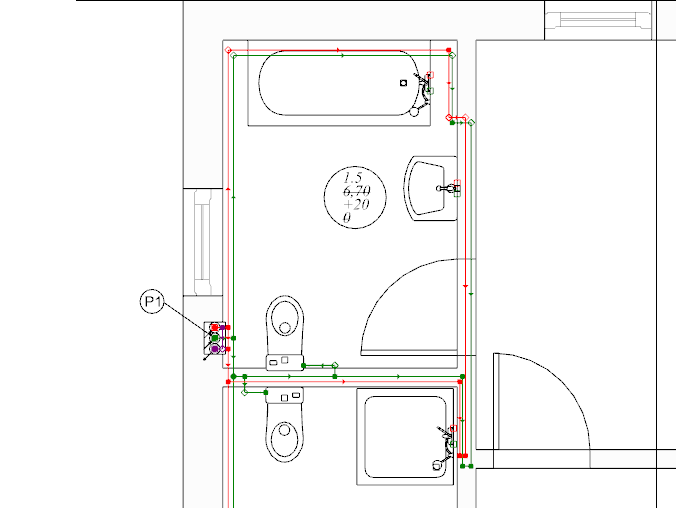
1.Creating a loop installation. - With your mouse, select the area with terminal units and choose Automatically connect terminal units in tee system .
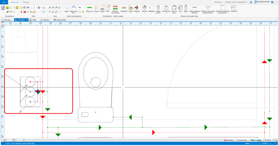
- If needed, modify pipe feed ordinates to evade doors. To do so, insert additional division points for the pipe feed passing through the door opening.
it is necessary to impose a correct ordinate. The correction of imposed values should be verified in the 3D view window.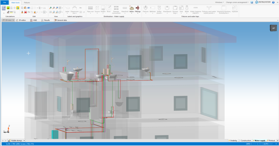
2. Omitting the door opening
- Verify if the circulation circuit has been closed properly on the storey.
3. Closing the circulation circuit on the first storey


Verification of the correctness of installation structure
- Verify correctness of the installation structure using the Check connections function (shortcut: Shift + F2).
- Verify correctness of the installation structure and find collisions using 3D view.
For more information, see: Verification of the correctness of installation structure
Calculations and diagnostics
- Perform Water supply systems by clicking on
 located in the Calculations section of the Main tools toolbar.
 - Check the Diagnostics window:
- fix Errors. For more information, see: How to eliminate: "Ring structure too complicated";
- correct Warnings. For more information, see: How to eliminate: "Too high water volume of h.w. network outside circulation loop".
- Verify calculation results.
For more information, see: Calculations and diagnostics
Generating schematic views
The schematic view will be generated automatically. For more information, see: Automatically generate schematic views.

BIM - Export of the installation to an IFC model
Specify the required settings and execute export of the installation using the IFC file export icon on the Main tools bar in the Printout and export section when the Printout editing scope is active.

For more information, see: BIM - Export of installation and construction data from the project to IFC models.
| If you have any comments on this article, please send us a short message at info@instalsoft.com. |
|---|