Designing mechanical ventilation installations
| Product | InstalSystem 5 |
| Type of article | DESIGNING LESSON |
| Source for translation | 2025-11-10 |
Scope of lesson
This article presents the basic design path for the Ventilation systems for residential buildings based on off-the-shelf components.
Modules and program configuration
InstalSystem 5 with the module:
- Mechanical ventilation for residential buildings.
The videos present the topics described in this article, but they aren’t a recording of this lesson.
Project file
The project file used in this lesson: Mechanical ventilation installation in residential building (example for the lesson).
Initial state
The project contains complete default data configured in the template file. The building structure has been elaborated on the basis of DWG layouts.
Steps to perform - Scenario I - сomplete design with air duct routing
Opening the project file
- When creating a new design, select from the list the template that contains the default data for the ventilation system or,
- Upload project file with existing building structure - minimum content is correct ordinates, slab thicknesses and manually created Rooms.
Editing the general project data
Fill in the default data in the General data window:
- Project scope - determine project scope: Ventilation systems.
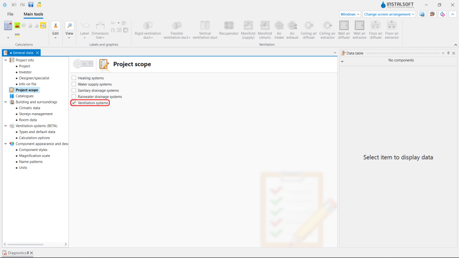
1. Project scope. - Catalogues – select and move necessary catalogues to the Catalogues in project: table. To speed up the selection, the filters can be used. For more information, see: Using catalogues and catalogues data in the project.
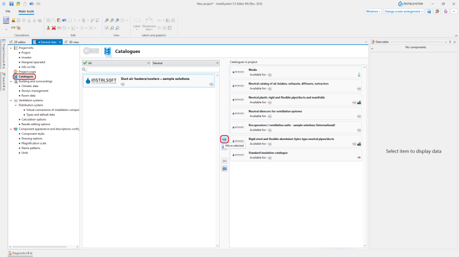
2. Catalogues. - General data editing:
- Storeys management:
- Create the appropriate number of Storeys / sub-levels (by interpreting from IFC or manually);
- Set storey data for Ventilation systems:
- Choose the manner of Distribution of ventilation system:
- Under upper slab,
- On lower slab;
- Improve the Default distance for ventilation elements.
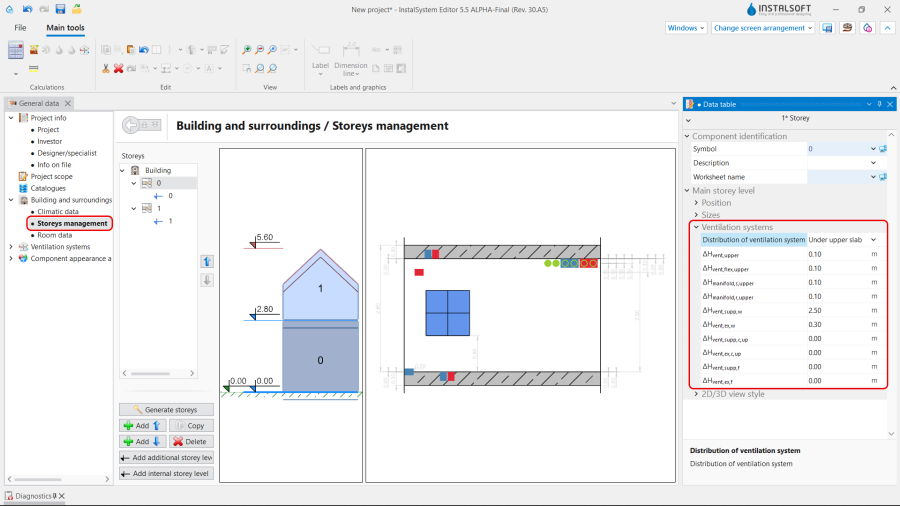
3. Storey data for Ventilation systems.
- Choose the manner of Distribution of ventilation system:
- (Optionally) Room data - for each / selected Room type, used in the project, set the values of:
- Exhaust air volume flux (V̇ex), Supplied air volume flux (V̇su) or Min. vent. air change rate (nmin);
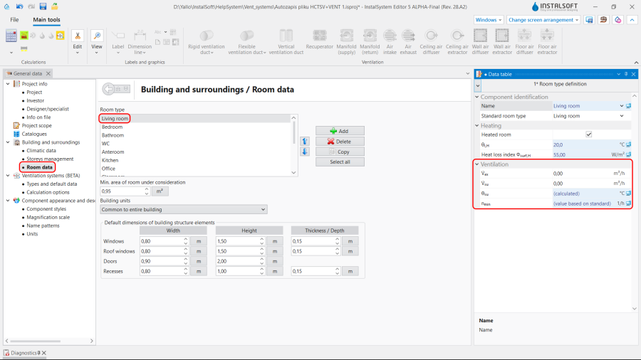
4. Room data General data.
- Exhaust air volume flux (V̇ex), Supplied air volume flux (V̇su) or Min. vent. air change rate (nmin);
- Ventilation systems / Types and default data – append default types:
- Default pipe types and insulation: Rigid duct;
- Default pipe types and insulation: Flexible duct;
- Default types: Other components:
- AHU / HRV,
- Supply ventilation manifold / Exhaust ventilation manifold,
- Supply air wall terminal / Exhaust air wall terminal, Supply air ceiling terminal / Exhaust air ceiling terminal, Supply air floor terminal / Exhaust air floor terminal,
- Duct silencer,
- Air intake & exhaust;
- Heat recovery efficiency: According to catalogue data, According to data for heat losses or User specified;
- (Optionally) control and adjustment of the default value of vmax, m/s in the specified locations of the installation.
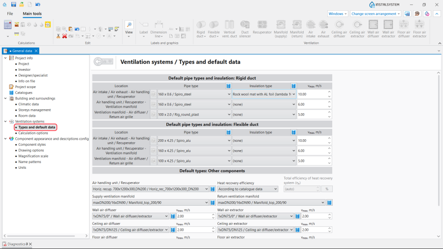
5. Types and default data.
- Ventilation systems / Calculation options:
- Select the Method of determining the amount of ventilation air;
- (Optionally) enable the function Check the minimum amount of ventilation air per resident;
- (Optionally) improve the value of θe - External temperature, design taken by the Air intake unit;
- (Optionally) set Permissible excess/deficiency of static pressure before the supply/exhaust air vent (Δpstat);
- (Optionally) adjust the value of Required minimum static positive pressure behind the air diffuser;
- (Optionally) adjust the value of Required minimum negative static pressure before the air extractor;
- (Optionally) turn on the function Allow fan gear selection outside the recommended range.
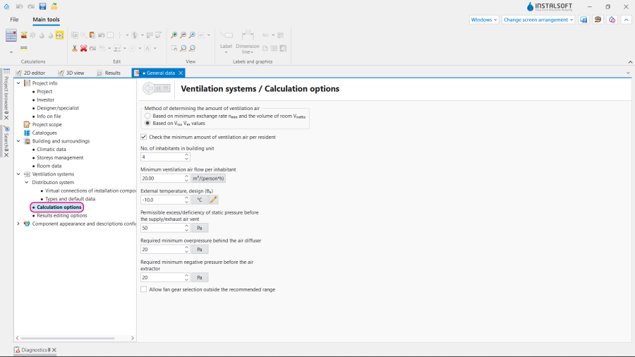
6. Calculation options.
- Storeys management:


Editing on the drawings
Editing the data
Set or modify the values of Exhaust air volume flux (V̇ex), Supplied air volume flux (V̇su) or Min. vent. air change rate (nmin) for each particular Room in the Data table in the Construction project scope.

Editing the installation
Carry out inserting and graphic editing operations using the AUTO and ORTO modes.
- Select editing scope Ventilation.
- Insert Ventilation elements:
- HRV,
- Manifold (supply) and Manifold (exhaust);
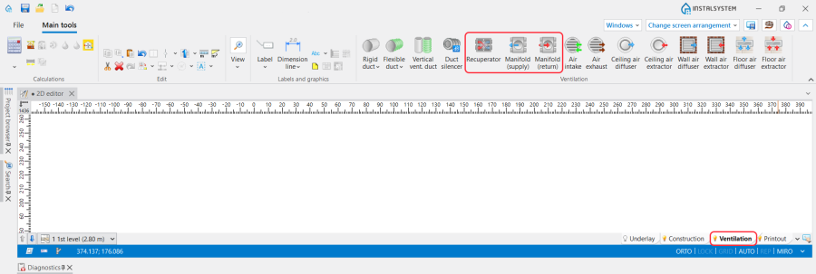
8. Insert HRV and Manifold (supply).
- Insert Ventilation terminals and indicate the Rotation angle, if necessary:
- Air intake,
- Air exhaust,
- Fresh air terminal (plenum, box, grille, supply diffuser).,
- Exhaust air terminal (plenum box, grille, exhaust diffuser),
- Air intake & exhaust;

9. Insert Ventilation terminals and indicate the Rotation angle.
- Insert Vertical vent. duct;
- Insert other elements of ventilation installation;

10. Insert other elements of ventilation installation. - Connect installation elements using Rigid duct or Flexible duct.


Note: If the Supply air ceiling terminal / Exhaust air ceiling terminal elements and the ducts, connecting them to the ventilation installation, are located on different Storeys, follow the steps described in the article How to arrange ventilation installation on the higher storey to serve the storey below.
Editing the element data
In the case of necessity modify the Ventilation elements data in the Data table window, in particular:
- Type of the Ventilation terminal;
- Type of the Supply air terminal / Exhaust terminal;
- V̇su / V̇ex for the Ventilation terminal;
- Distance from ceiling (slab) / Elevation for the Ventilation elements;
- Pipe type / Size for the Ventilation ducts;
- Type of Insulation and Location for insulation purposes. Note: During Calculations the thickness of the Insulation is automatically determined taking into account the Location of the the duct in a heated or unheated space.
Verifying the correctness of the installation structure.
- Verify the correctness of the connections of the installation components using the Check connections function (Shortcut: Shift + F2);
- Verify the correctness of the installation structure using the 3D view;
- Adjust the layout of the Ventilation ducts according to external factors, e.g. passages through walls, overlaps with other installations.
Running the calculations
- Start the calculation of the Ventilation systems by clicking
 in the Calculations section of the toolbar;
 - Сheck messages the Diagnostics window;
- In the case of necessity verify and adjust the installation:
- the error Fan does not provide the required air flow. V̇=%s [m3/h], V̇min=%s [m3/h], V̇max=%s [m3/h] is indicated:
- choose other type of AHU / HRV with appropriate parameters;
- the warning Fan pressure (%s) smaller than required in the installation (%s) is detected:
- choose other type of AHU / HRV with appropriate parameters;
- the warning Maximum air flow velocity exceeded (%s m/s > %s m/s) appears:
- increase the Diameters / Sizes of the Ventilation ducts,
- select other types of Supply air terminal / Exhaust terminal with the opportunity of connecting and placing additional air ducts,
- add and connect more Supply air terminal / Exhaust terminal,
- modify vmax, m/s;
- the warning Unbalanced ventilation air flow (ΣV̇su=%s m3/h, ΣV̇ex=%s m3/h) is displayed:
- correct the values of V̇su and V̇ex.
- the error Fan does not provide the required air flow. V̇=%s [m3/h], V̇min=%s [m3/h], V̇max=%s [m3/h] is indicated:
Verification of results
- After calculations, the system layout should be verified visually by means of the 3D view;
- If the calculations end with at least one error, the layout may be unreliable;
- The data of each Ventilation element can be verified directly in the drawings by means of component labeling and hints containing tables with basic parameters.
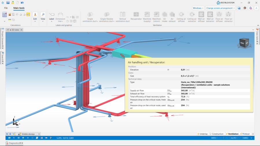
11. Visual verification in the 3D view window.

Results tables
Use the tables presented in the Results window to verify the parameters of the installation:
- Ventilation ducts;
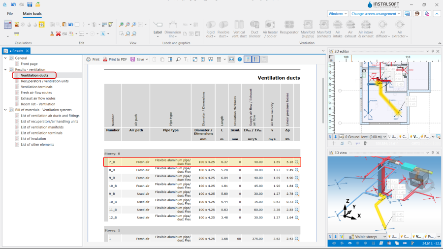
12. Ventilation ducts. - HRV's / AHU's;
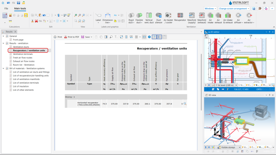
13. HRV's / AHU's. - Ventilation terminals;
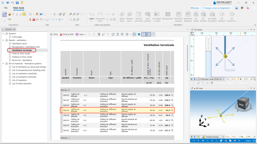
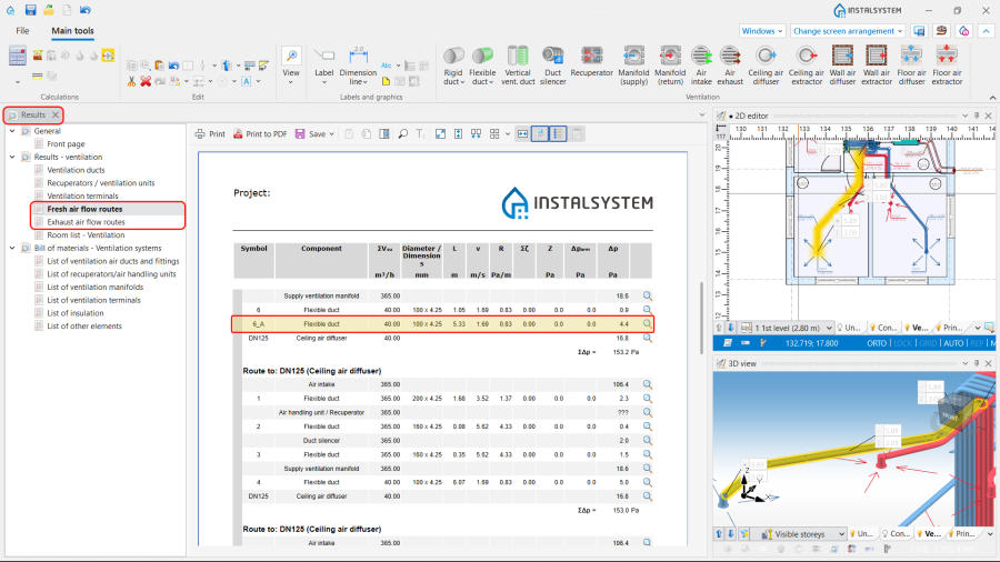
14. Ventilation terminals. - Fresh air flow routes and Exhaust air flow routes - the tables show airflow routes, values of airflow and pressure losses for each particular installation element.
15. Results - ventilation. - Room list - Ventilation;

16. Room list - Ventilation. - Bill of materials - Ventilation systems;
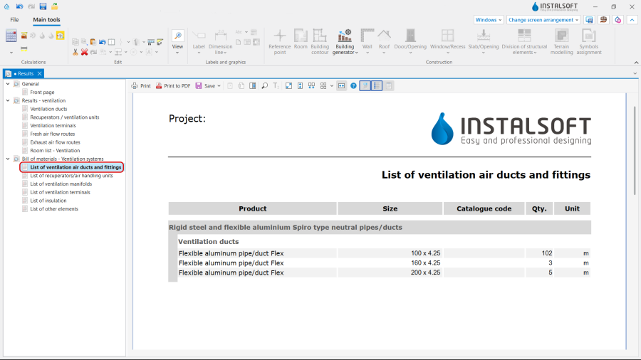
17. Bill of materials - Ventilation systems.


Every item of the installation presented in the Results tables can be found in active windows by using ![]() icon.
icon.
For more information, see: Presentation of the calculations result.
Preparing drawings for export/printing
- To have the results for Ventilation installation elements included in the printout of a drawing, appropriate labels must be inserted For more information, see: Preparation of drawings for export / printing.
- Completed drawings can be printed and/or exported For more information, see: Export / print results and drawings.
Steps to perform - Scenario II - quick design with virtual connections
Opening the project file
Steps to perform just like in Scenario I - Opening the project file.
Editing the general project data
Fill in the default data in the General data window:
- Project scope - determine project scope;
- Catalogues – select and move necessary catalogues to the Catalogues in project: table;
- Storeys management - set basic parameters;
- Virtual connections of installation components tab:
- Turn ON the function Create virtual connections when there are no graphical connections,
- Indicate, if the List virtual components is required,
- Modify, if necessary, the Length coeff. for flexible virtual ducts and Length coeff. for rigid virtual ducts,
- Specify the method of determination the Number of ducts connected to air terminal,
- Select Flexible duct or Rigid duct will be used for virtual connections with Ventilation elements, depending on their location;

18. Virtual connections of installation components.
- Ventilation systems / Types and default data – append default types for the Ventilation elements, used in the project;
- Ventilation systems / Calculation options - set the necessary parameters.

For more information, see: Scenario I - Editing the general project data.
Editing on the drawings
Editing the data
Steps to perform just like in Scenario I - Editing the data.
Editing the installation
Steps to perform just like in Scenario I - Editing the installation, except for the application of Duct silencer, Air heater / cooler, Vertical vent. duct and Ventilation duct elements.
Editing the element data
If necessary, correct the Ventilation elements data in the Data table window, in particular:
- Type of the Ventilation terminal;
- Type of the Supply air terminal / Exhaust terminal;
- V̇su / V̇ex for the Ventilation terminal;
- Distance from ceiling (slab) / Elevation for the Ventilation elements;
- Review and correct, if necessary.
Verifying the correctness of the installation structure.
- Verify the correctness of the connections of the installation components using the Check connections function (Shortcut: Shift + F2) and if it's necessary:
- the assignment of a particular Supply air terminal / Exhaust terminal to the Manifold (supply) / Manifold (exhaust), with which they are virtually connected,

19. Assignment to the manifold. - the assignment of a particular Manifold (supply) / Manifold (exhaust) to the HRV / AHU, with which they are virtually connected,

20. Assignment to the HRV / AHU. - the assignment of the Air intake / Air exhaust to the HRV / AHU, with which they are virtually connected,

21. Assignment of the Air intake / Air exhaust.
- the assignment of a particular Supply air terminal / Exhaust terminal to the Manifold (supply) / Manifold (exhaust), with which they are virtually connected,
- Verify the correctness of the installation structure using the 3D view.


Running the calculations
- Start the calculation of the Ventilation systems by clicking in the Calculations section of the toolbar;
- Сheck messages the Diagnostics window;
- In the case of necessity verify and adjust the installation:
- the warning Maximum air flow velocity exceeded (%s m/s > %s m/s) appears:
- select other types of Supply air terminal / Exhaust terminal with the opportunity of connecting additional air ducts,
- modify Number of ducts connected to air terminal in the Data table

22. Number of ducts connected to air terminal. - add more Supply air terminal / Exhaust terminal.
- the warning Maximum air flow velocity exceeded (%s m/s > %s m/s) appears:

For more information, see: Scenario I - Running the calculations.
Verification of results
Steps to perform just like in Scenario I - Verification of results.
Preparing drawings for export/printing
Steps to perform just like in Preparing drawings for export/printing.
| If you have any comments on this article, please send us a short message at info@instalsoft.com |
|---|