Designing installations with flat stations
| Product | InstalSystem 5 |
| Type of article | DESIGNING LESSON |
| Source for translation | 2024-01-31 |
Scope of lesson
The article shows how to design installations with flat stations. Flat station may become a connection point for an apartment heating and sanitary system.
Non simultaneous medium intake for domestic hot water heating is taken into consideration while dimensioning the flat station feeding system. Flat station type and size are chosen by the user, meanwhile the program diagnoses whether a given flat station is able to deliver enough output to the heating system to which it is connected and for declared/calculated domestic hot water parameters.
Modules and program configuration
- InstalSystem 5 package with the following modules:
- Flat stations
- Heating systems
and as an option: - Radiant systems - if the station is supposed to supply an apartment radiant system with heating medium
- Tap water systems - if calculations for the flat station and the supply system should include flow rate of a sanitary system designed with InstalSystem 5
- Flat stations
The videos present the topics described in this article, but they aren’t a recording of this lesson.
Project file
The project file used in this lesson: Water supply system and radiant heating system with use of flat stations in a residental building (example for the lesson) - multi-branch project.
Initial state
The project contains a building structure (storeys, rooms) and a storey plan drawing.
Room heat load values for heating has been declared.
For more information, see: Preparation of building structure.
For more information, see: Import underlay files.
Steps to perform - Scenario I - value of Hot water outflow declared manually
Defining catalogues and general data
General data window
- Catalogues tab – read into the project the catalogue containing flat stations.
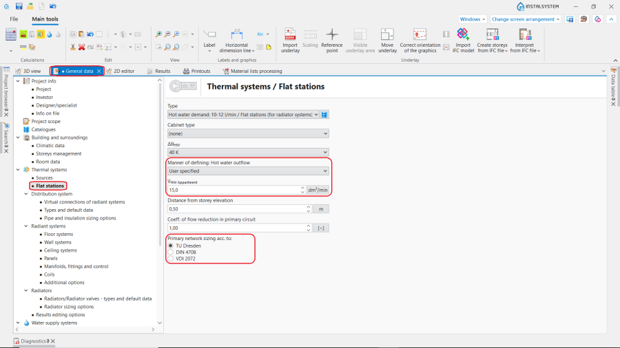
- Thermal systems / Flat stations tab - complete Type and other general data, in particular:
- ΔθHW (Hot water heating degree),
- Manner of defining: Hot water outflow: "User specified" - the V̇HW Appartment (Hot water outflow) value is entered manually by the user in the field below and in the Data table window after marking the station in the drawing,
- choose the method of sizing the supply network (Primary network sizing acc. to: TU Dresden, DIN 4708 or VDI 2072)
1. Scenario I - value Hot water outflow declared manually.

Editing installation
Inserting and operations on 2D view
- Choose the Convectional/Rad.-floors,walls editing scope.
- Insert a flat station using the Flat station button. Rotate if needed.

2. Inserting Flat stations - Convectional/Rad.-floors,walls editing scope.

Verification and completion of installation data
- In the Data table window, verify data of each Flat station element in particular in scope of:
- Type,
- Distance from storey elevation,
- V̇HW Appartment (Hot water outflow),
- ΔθHW (ATTENTION! The input temperature of domestic hot water feeding the flat station results from properties of a given manufacturer's heat exchanger, and it usually amounts to 10°C),
- accessories and their data.
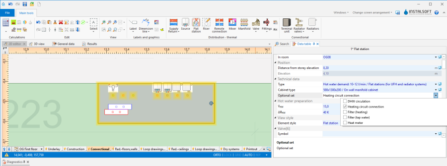
3. Editing Flat stations - Data table.

Connecting flat stations with installation
- Connect heating system supply and return pipe-runs on the primary side to the connecting points indicated by the symbol
 . For more information, see: Connecting storeys with the "Stack" element.
 - Connect Pipe feeds route or pipe feeds themselves to the manifold
 . Radiant installation should be created primarily according to the following article:Designing of radiant heating floor and wall installation.
 - Connect radiator (domestic) heating installation supply and return pipe-runs to the connection points indicated by the symbol
 . The heating installation should be primarily prepared according to the following article: Designing heating systems with convective radiators.
(optional) Copying Flat station elements with/without apartment systems on other storeys
Installation copying
- Select Flat station and/or chosen system elements.
- Copy selected elements on neighbouring storeys with the function Copy selected elements to the storey above/Copy selected elements to the storey below.
Creating a copy of a whole storey
General data window
- Building and surroundings / Storeys management tab - select a storey and press Copy.
Verification of installation structure correctness
- Verify correctness of the installation structure with the Check connections function (shortcut: Shift + F2).
- Verify correctness of the installation structure and detect collisions using 3D view.
For more information, see: Verification of the correctness of installation structure.
Calculations and results verification
- Perform full calculation by clicking the calculator icon
 situated in the Calculations section on the toolbar.
 - Verify and improve diagnostics messages, in particular:
- flow rate on the heat exchanger primary side - if it exceeds the admissible value, such an error may occur:

4. Heat exchanger out of range.
in such a case, correct input data (θs,H and/or V̇HW Appartment and/or ΔθHW) or choose a different heat exchanger size manually. - The Vs value calculated for the water supply installation connected to the flat station is higher than the value entered in the V̇HW Appartment field. Calculations further take into account the entered value. - the hint relates to the determining the required pressure at the source of the water supply system. The key parameter in such calculations for installations with flat stations is Hot water outflow.

5. Vs calculated by the water supply module is higher than V̇HW Appartment entered manually.
The value V̇HW Appartment set in the General data window or in data table of Flat station affects the pressure losses in the primary heating circuit supplying the flat stations and the heating output of heat exchanger.
For the calculation of pressure losses in the tap water circuit the value Vs computed accordingly Tap water systems module is taken, regardless of which method of calculation is chosen.
The value Vs is typically higher than the value V̇HW Appartment. This is the reason of overestimation of the required pressure in the cold water source.
The following steps can be taken to reduce the required pressure in the cold water source: - Adjustment of Normative outflow (HW)(Qn HW) for single points of use;
- Exclusion of value for the selected point by specifying Not considered in the Demand type field;
- Choosing for calculations the water supply standard DIN 1988-300.
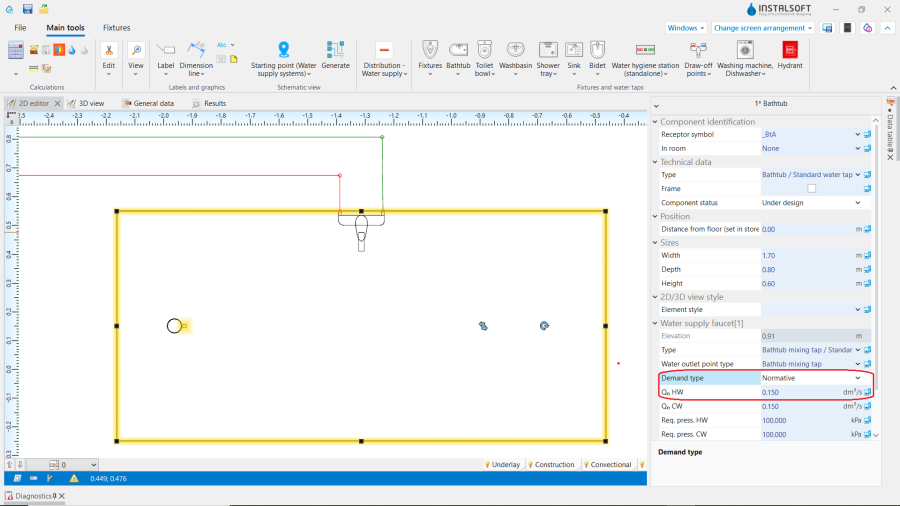
6. Normative outflow (HW), Demand type.
- flow rate on the heat exchanger primary side - if it exceeds the admissible value, such an error may occur:
- Check calculation results, in particular:
- Number of Flat stations connected to the supply or return Pipe-run and their operating mode:
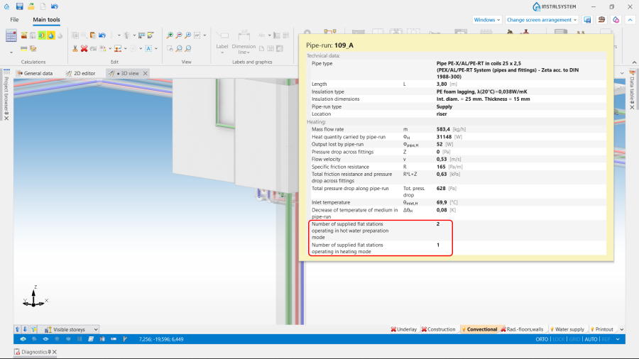
7. Number of flat stations and their operating mode. - Required heat source output;
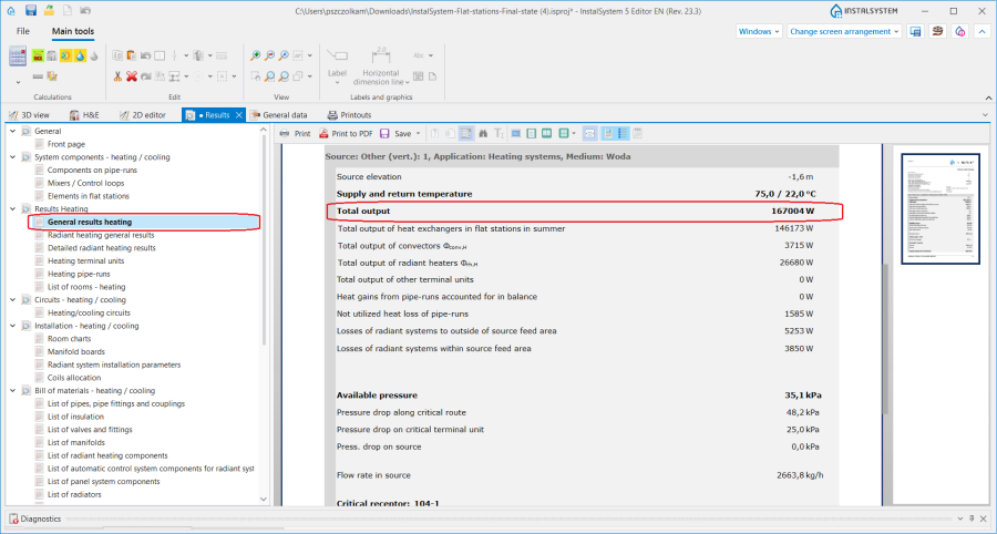
8. Required heat source output.
- Number of Flat stations connected to the supply or return Pipe-run and their operating mode:
- Total output of heat exchangers in flat stations in summer;
Output of the heat source beyond the heating season presented as a separate item in the General results heating sheet; based on that it is possible to reduce the heat quantity ordered during the summer season from the heat supplier.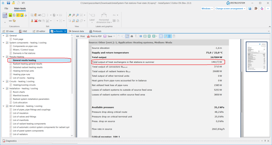
9. Total output of heat exchangers in flat stations in summer. - (in selected versions) the required buffer tank capacity;
- Elements in flat stations;
The result sheet shows the components and their parameters in the individual circuits inside the station.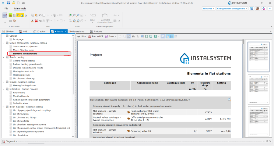
10. Elements in flat stations. - list of flat stations and their components.
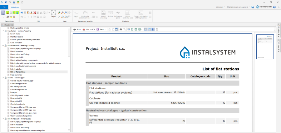
11. List of station components.


For more information, see: Calculations and diagnostics.
Attention! When analysing the calculation results obtained, it should be noted that the sum of the outputs for the central heating terminal units and the domestic hot water exchangers is not equal to the obtained value of Total output for the heat source.
This is due to the fact that the values of Total output of convectors Φconv,H, Total output of radiant heaters Φrh,H and Total output of other terminal units presented in the printout represent the sum of the capacities of all the central heating terminal units in the system, including those connected to the Flat station components operating in the domestic hot water heating mode.
When calculating the output of the heat source, the program assumes that if Flat station is operating in the domestic hot water heating mode, then it is not supplying the residential part of the central heating system. Therefore, when determining the value of Total output the output required for the domestic hot water heat exchangers operating in this mode (the number of Flat station components results from the selected calculation method) and the output required for central heating of other stations in the system are included.
Generating schematic views
The schematic view will be generated automatically. For more information, see: Automatically generate schematic views.

Printout/export of results
- Print/export drawings.
- Print/export tables.
For more information, see: Export / print results and drawings.
BIM - Export of the installation to an IFC model
Specify the required settings and execute export of the installation using the IFC file export icon on the Main tools bar in the Printout and export section when the Printout editing scope is active.

For more information, see: BIM - Export of installation and construction data from the project to IFC models.
Steps to perform - Scenario II - Hot water outflow value calculated by the Tap water systems module
Defining catalogues and general data
General data window
- Project scope tab - check Water supply systems.
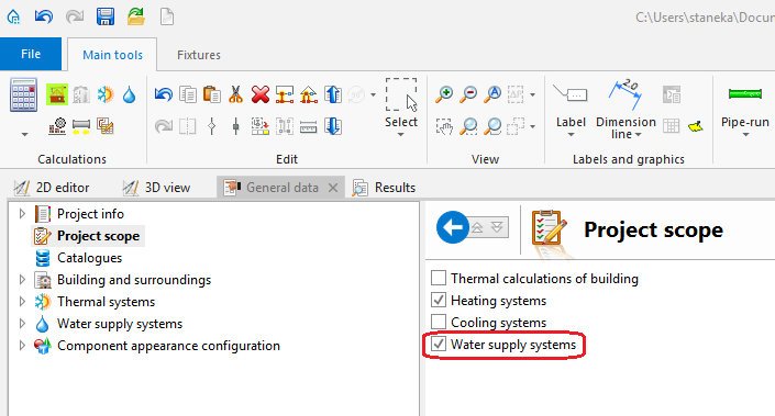
14. Indicated project scope. - Catalogues tab – read into the project the catalogue containing flat stations.
- Thermal systems / Flat stations tab - complete Type and other general data, in particular:
- ΔθHW (Hot water heating degree)
- Manner of defining: Hot water outflow: "Acc. to calc. of the module: Water supply systems" - the value of V̇HW Appartment (Hot water outflow) will be calculated based on the flow balance of the water supply system connected to the station, according to the Tap water systems calculation standard selected in the module.
- choose the method of sizing the supply network (Primary network sizing acc. to: TU Dresden, DIN 4708, VDI 2072 or DIN 1988-300).
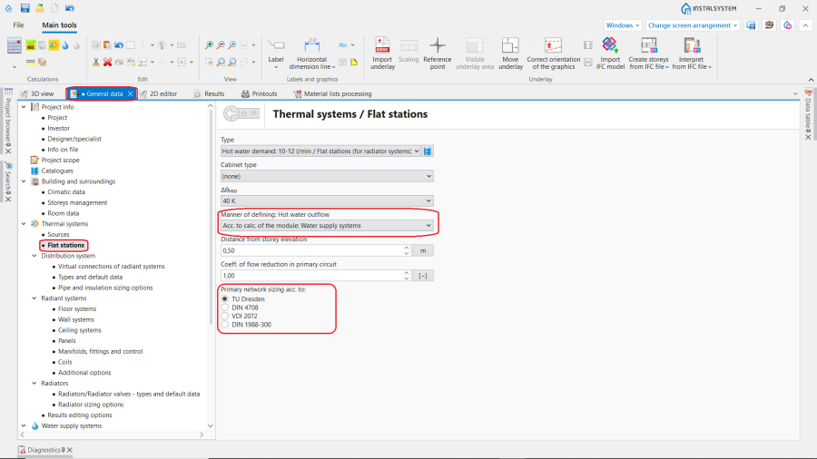
15. Scenario II - Hot water outflow value calculated by the Tap water systems module.


Editing installation
Inserting and operations on 2D view
- Choose the Water supply editing scope.
- Insert the flat station using the Flat station icon and rotate if needed.
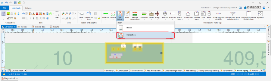
16. Inserting Flat stations - Water supply.

Verification and completion of installation data
- In Data table, verify data of each Flat station element in scope of:
- Type,
- Distance from storey elevation,
- V̇HW Appartment (Hot water outflow). If, in the General data window, the Acc. to calc. of the module: Water supply systems option is selected, this value is calculated automatically. But it can be changed manually for a particular Flat station. ATTENTION! In this case the value V̇HW Appartment has an impact on the further calculations in this way:
- if Vs (Volumetric flow rate) calculated in accordance with the water supply module based on the selected standard is less than or equal to the value V̇HW Appartment entered manually in the Data table, then the value Vs calculated by the water supply module will be taken into account;
- if Vs calculated in accordance with the water supply module based on the selected standard is higher than the value V̇HW Appartment entered manually in the Data table, then the value V̇HW Appartment entered manually will be taken into account.

17. Vs calculated by the water supply module is higher than V̇HW Appartment entered manually.
- ΔθHW (ATTENTION! The input temperature of domestic hot water feeding the flat station results from properties of a given manufacturer's heat exchanger, and it usually amounts to 10°C),
- accessories and their data .
18. Editing Flat stations - Data table.

Connecting flat stations with installation
- Connect heating system supply and return pipe-runs on the primary side to the connecting points indicated by the symbol . For more information, see: Connecting storeys with the "Stack" element.
- Connect Pipe feeds route or pipe feeds themselves to the manifold . Radiant installation should be created primarily according to the following article:Designing of radiant heating floor and wall installation.
- Connect radiator (domestic) heating installation supply and return pipe-runs to the connection points indicated by the symbol . The heating installation should be primarily prepared according to the following article: Designing heating systems with convective radiators.
- Connect to the flat station, at points marked with the
 symbol, cold water pipe-run for the water supply system and system distribution, i.e. Hot water and Cold water pipe-runs, in accordance with Designing of water supply system installation.
Verification of installation structure correctness
Steps to perform just like in Scenario I - value Hot water outflow declared manually.
Calculation and results verification
Steps to perform just like in Scenario I - value Hot water outflow declared manually.
Generating schematic views
Steps to perform just like in Scenario I - value Hot water outflow declared manually.
Printout/export of results
Steps to perform just like in Scenario I - value Hot water outflow declared manually.
BIM - Export of the installation to an IFC model
Steps to perform just like in Scenario I - value Hot water outflow declared manually.
Possible differences between the results obtained in the program and from manual calculations
Applied method of calculating non-simultaneous demand coefficients
The method used by the program for calculations can be indicated in the Results window.

Methods alternatively to be used for calculations - Scenario I:
- TU Dresden (default)
- DIN 4708
- VDI 2072
Methods alternatively to be used for calculations - Scenario II:
- TU Dresden (default)
- DIN 4708
- VDI 2072
- DIN 1988-300
Required heating output of the heat exchanger
In the program, the heat exchanger output is determined from the characteristics saved in flat station catalogues. Potential differences in the calculation results (vs manual calculations) can be caused by:
- different source materials used at the stage of the program catalogs preparation and the materials used by the engineer;
- inaccuracy of the heat exchanger output readout from the diagram;
- comparison of the output results from the program with manual calculations of the output according to formulas based on flow rate, temperature and specific heat of the medium.
Temperature and flow rate of the medium in the return sections of the installation
When determining the temperature and flow rate of the installation, the program takes into accurratly number of flat stations operating in hot water preparation mode and other providing medium to domestic heating installations. Accordingly calculates the flows and return temperature in each return pipe-run in primary circuit.
Manual methods are usually simplified and assume constant (and equal for all flat stations) return temperature.
Manner of defining: Hot water outflow
The method used in the program may base (as one of the options) on accurate calculations of tap water installation, in accordance to the standard. Manual calculations base on imposed value of Hot water outflow. In this case the value V̇HW Appartment determines which of the parameters will be used in further calculations: V̇HW Appartment or Vs. For more information, see: Verification and completion of installation data.
Other possible reasons of differences
- Rounding and accuracy of physical values in the program;
- Adoption of different boarder conditions (e.g.: medium temperature when considering specific heat, receiver output without considering medium temperature drop);
- Using different standards and methods to determine peak flow rate;
- Specific of the installation (e.g.: ring installations);
- Adopted rules of calculating obtained outputs.
influence on flows in primary network
In the case of a necessity to adjust or modify the flows in primary network this can be achieved by the following ways:
- Changing the value of Coeff. of flow reduction in primary circuit
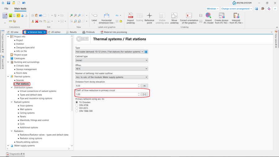
20. Coeff. of flow reduction in primary circuit. - Changing Pipe and insulation sizing options for Thermal systems
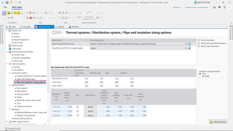
21. Pipe and insulation sizing options for Thermal systems.


and for Water supply systems

- Placing on the installation Reduction point element.
| If you have any comments on this article, please send us a short message at info@instalsoft.com |
|---|